80S-15贴片机.pdf - 第324页
9 Revolver Head SIPLACE 80S/F/G Service Manual Edition 04/97 9 - 40 The rotati onal mo vement of the sc rewdrive r is rest ricted b y the s top nippl e on th e face of th e motor gear- wheel. Afte r each r otatio n of 18…
SIPLACE 80S/F/G Service Manual 9 Revolver Head
Edition 04/97
9 - 39
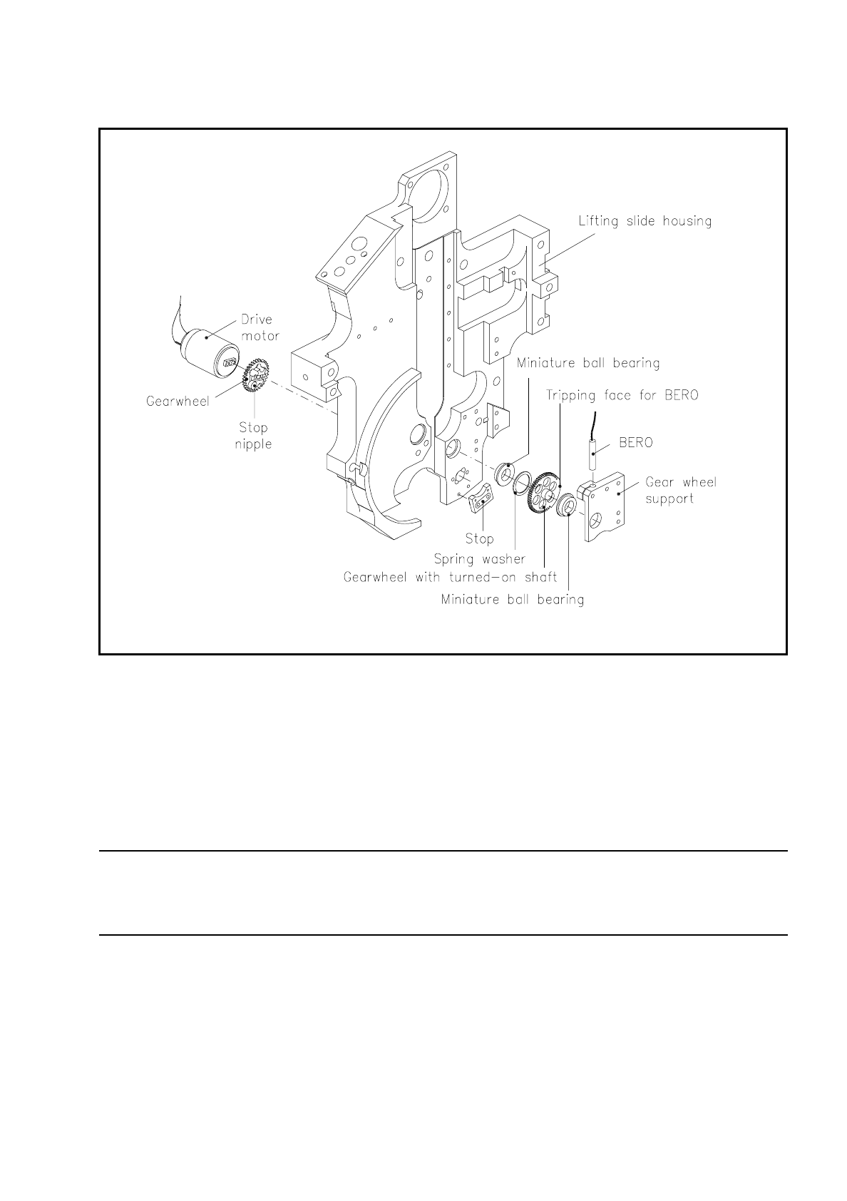
Fig. 9.5.12 Screwdriver unit 2
The drive motor sits in the hole in the position of revolver head station 3.
The gearwheel on the motor shaft meshes with the teeth of the gearwheel with turned-on shaft which is
mounted at each end in 2 miniature ball bearings. The miniature ball bearing at the revolver head end is
accommodated in the gearwheel support. The screwdriver unit blade engages with the slot in the segment at
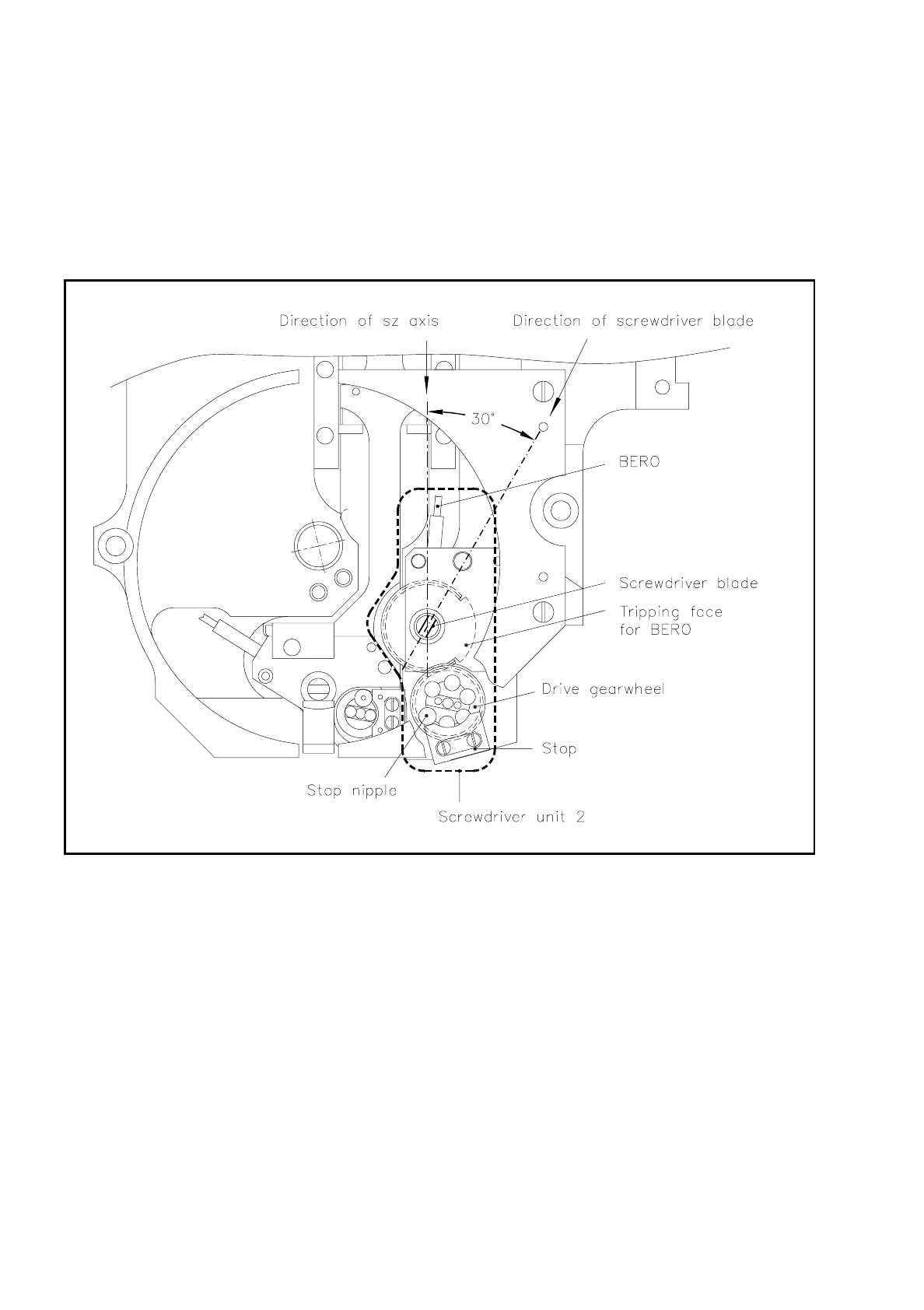
revolver head station 3. The screwdriver unit blade must be at an angle of 30° to the sz axis (see Fig. 9.5.13).
NOTE
If the screwdriver unit blade does not make an angle of 30° with the sz axis, the screwdriver unit blade will not
be able to slide in die groove of the cam. The revolver head will jam.
The bero is inserted from above into the hole in the gearwheel support and fixed at the corresponding trigger-
ing distance. The toothless section of the gearwheel circumference is used for as a sensing face for the bero
and triggers the end message for rotation of the screwdriver.
9 Revolver Head SIPLACE 80S/F/G Service Manual
Edition 04/97
9 - 40
The rotational movement of the screwdriver is restricted by the stop nipple on the face of the motor gear-
wheel. After each rotation of 180° the stop nipple will lie up against the stop. The screwdriver is fixed in the
end position by a holding current.
Screwdriver unit 2 is activated as soon as the end message of the dR revolver head axis for "Revolver head
division reached" is received.
Fig. 9.5.13 30° - position of the screwdriver unit blade with respect to the sz axis in screwdriver unit 2
The rotational movement for the open or closed segment is determined similarly to the procedure shown in
Fig. 9.5.11.
9.5.8 Circular Arc Guidance for the Segments
The circular arc guide holds the segments at a defined clearance from the revolver head center point which is
also the center of rotation. While the revolver head turns the segment ball bearings roll along the circular inner
faces of the fixed and removable circular arc guides (link). There are breaks in the circular arc guides in each
case at the top, that is, at revolver head station 7 and at the bottom, that is, at revolver head station 1.
SIPLACE 80S/F/G Service Manual 9 Revolver Head
Edition 04/97
9 - 41
You can insert or remove the segments at revolver head station 7. In revolver head station 1, the pick-up and
placement station the lifting slide moves the segment vertically once the ball bearing of the segment has
moved into the segment claw.
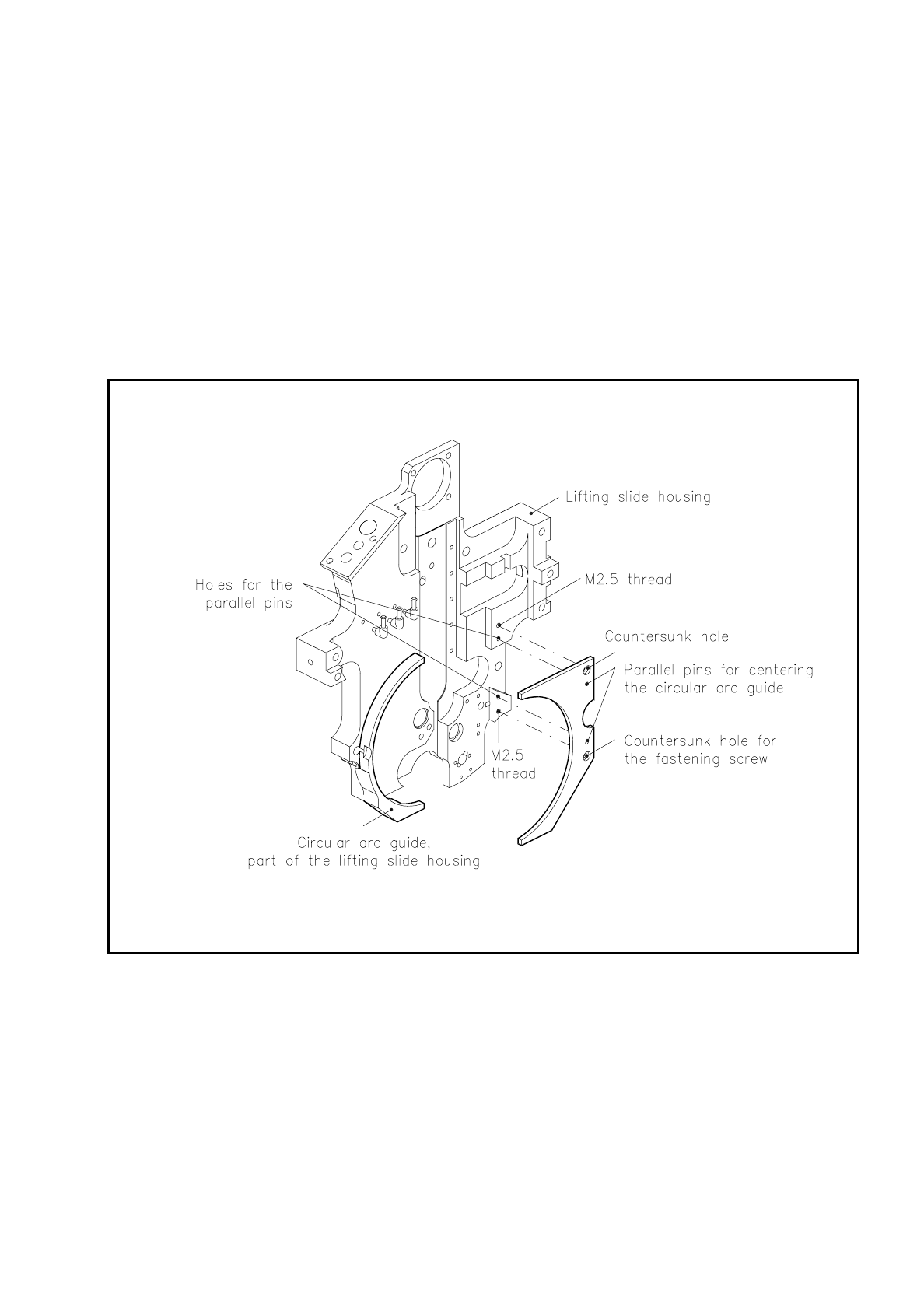
The circular arc guide consists of two halves:
–
one guide integrated into the lifting slide housing and
–
a removable guide (link).
It is fastened with two M2.5 countersunk screws to the lifting slide housing. Two parallel pins center the
removable circular arc guide (see Fig. 9.5.14).
Fig. 9.5.14 Circular arc guide of the segments