80S-15贴片机.pdf - 第345页
SIPLACE 80S/F/G Service Manual 9 Revolver Head Edition 04/97 9 - 61 The glued -on runni ng disk has 12 holes for the vacuum duc ts. The addi tional depressi ons crea te a maxim um overla pping betwe en the vac uum ducts …

9 Revolver Head SIPLACE 80S/F/G Service Manual
Edition 04/97
9 - 60
The 12 guide shafts and the ball cages running on the webs have the function of guiding the segments. The
individual segments are evacuated via the vacuum ducts.
The 12 guide shafts are let into blind holes in the revolver head housing.
The 12 vacuum tubes are also let into holes in the revolver head housing. From the side facing the lifting slide
housing 12 holes intersect with the vacuum tubes holes and form the 12 vacuum ducts. A disk centered with
two parallel pins and which has 12 holes for the vacuum ducts runs on the vacuum distributor coupling in
order that the vacuum is constantly maintained at the individual circuits.
The 12 webs are fastened in each case with two M1.4 fillister head screws to the revolver head housing. The
ball cages slide along the webs. In each guide strip there is a hexagon bolt which engages with the cage slot
and thus restricts the movement of the cage (see Fig. 9.6.11).
NOTE
The revolver head can only be removed or fitted in the factory.
9.6.6 Vacuum Distributor Piece
The vacuum distributor piece connects the three vacuum ducts in the lifting slide housing with the vacuum
circuits of the revolver head. There are a total of three vacuum circuits:
–
Holding circuit
The holding circuit includes revolver head stations 2 and 4 - 12. During the revolver head cycle the
vacuum is maintained in the individual segments. Pick-up components are held by underpressure to the
nozzle.
–
Pick-up and placement circuit
In revolver head station 1, components are sucked up by underpressure and blown off for placement.
–
Ejection circuit
In revolver head station 3
●
a defective component is ejected;
●
during the pick-up cycle the component shape "Good or bad nozzle contact" is tested;
●
the degree of nozzle contamination is checked;
●
the segment is checked for leaks.
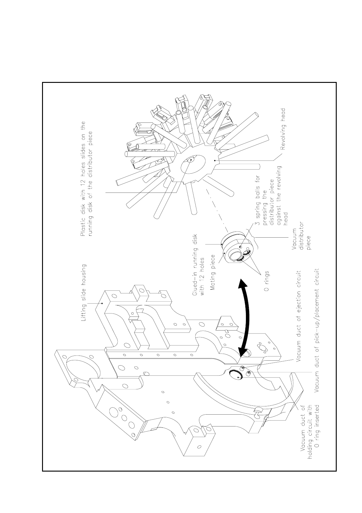
The vacuum distributor piece consists of the following components (see Fig. 9.6.13):
–
mating piece
–
running disk, glued vacuum-tight to the mating piece
–
1 o-ring 9 x 1
–
1 o-ring 4 x 1.2 in each case for pick-up and placement circuit and for ejection circuit
SIPLACE 80S/F/G Service Manual 9 Revolver Head
Edition 04/97
9 - 61
The glued-on running disk has 12 holes for the vacuum ducts. The additional depressions create a maximum
overlapping between the vacuum ducts of the running disk and the plastic slip disk in the revolver head so that
when the revolver head turns there can be no loss of vacuum in the individual vacuum circuits.
Fig. 9.6.13 Vacuum distributor piece
9 Revolver Head SIPLACE 80S/F/G Service Manual
Edition 04/97
9 - 62
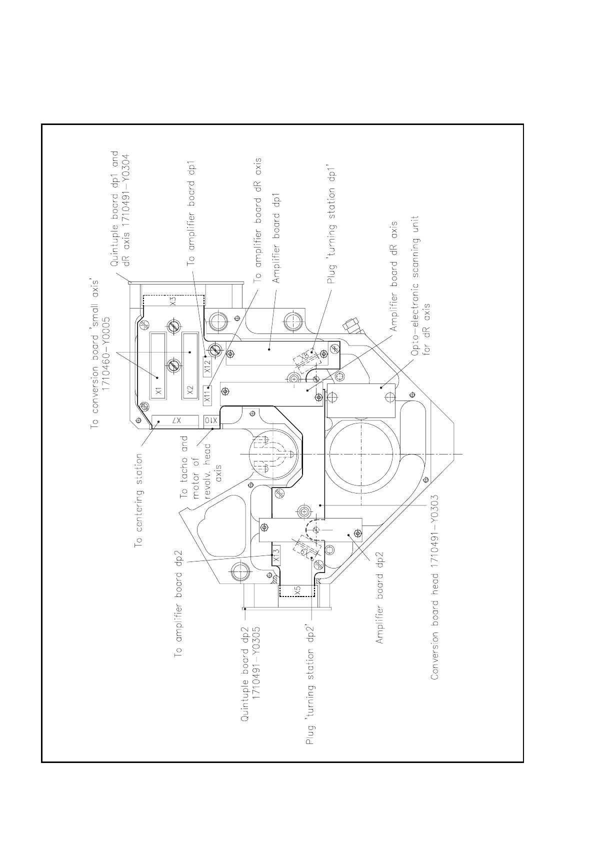
9.6.7 Conversion Board "Head" 1710491-Y0303
Fig. 9.6.14 Conversion board “Head“ - 1710491-Y0303