80S-15贴片机.pdf - 第340页
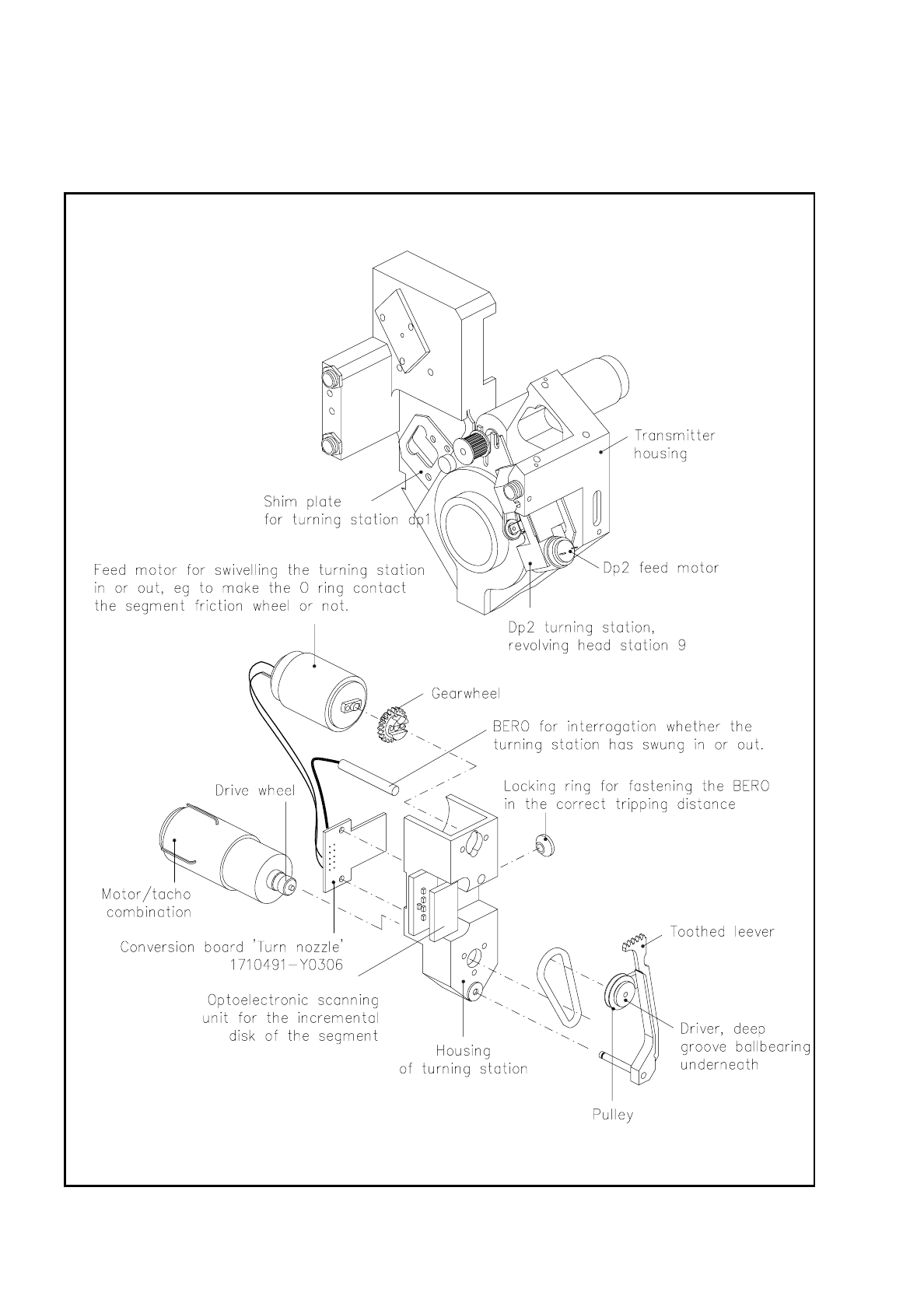
9 Revolver Head SIPLACE 80S/F/G Service Manual Edition 04/97 9 - 56 9.6.4 Tur ning Station dp2 Fig. 9.6.10 Pos ition and structure of turning station dp2
SIPLACE 80S/F/G Service Manual 9 Revolver Head
Edition 04/97
9 - 55
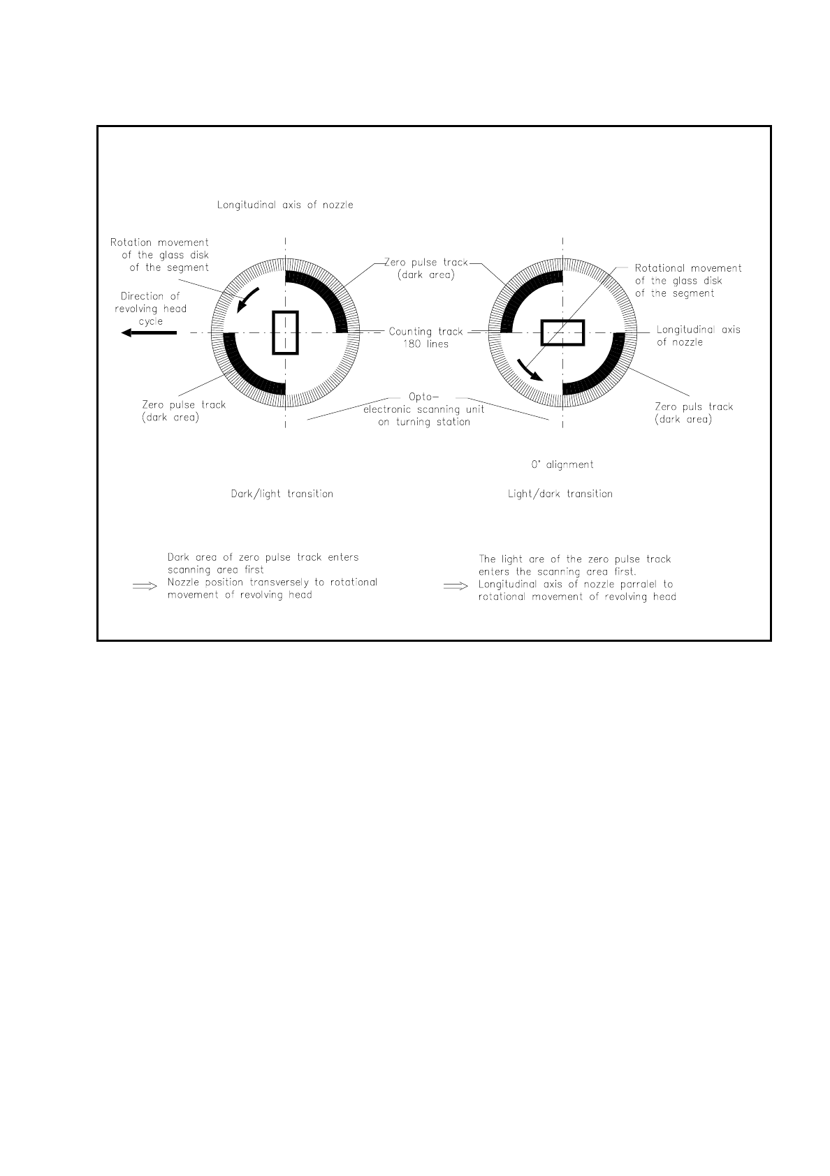
Fig. 9.6.9 Position of the nozzle longitudinal axis with respect to the direction of revolver head movement
These analog signals are amplified with the amplifier board on the encoder housing front (see Fig. 9.6.4) and
multiplied on the quintuple board and converted into square-wave signals for the purposes of evaluation in the
axis controllers. The track signals are illustrated in Fig. 9.6.15.
Fig. 9.6.10 shows the position of the longitudinal axis of the nozzle with respect to the zero pulse track.
Depending on whether the opto-electronics registers a light-dark or dark-light transition of the zero pulse
track, the current nozzle position is detected and then the nozzle turned into the required position.
The resolution of the electronic positioning system is 10 digits per degree.
9 Revolver Head SIPLACE 80S/F/G Service Manual
Edition 04/97
9 - 56
9.6.4 Turning Station dp2
Fig. 9.6.10 Position and structure of turning station dp2

SIPLACE 80S/F/G Service Manual 9 Revolver Head
Edition 04/97
9 - 57
Turning station dp2 is located in revolver head station 9. It turns the nozzle with or without a component into
the pick-up or placement position. It is identical in design with turning station dp1.
The structure and function of turning station dp2 are as described in Section 9.6.3, but with the following
exceptions:
–
Turning station dp1 turns the component into the required measurement position for the mechanical
centering station.
–
Turning station dp2 performs the following functions:
●
If a nozzle with a picked-up component arrives at revolver head station 9 during the first revolver head
cycle with rotational, CRDL or centering errors, the component will now be turned into the required
placement position. If the polarity of the component happens to be incorrect it will be rotated until it is
in the correct position for placement.
●
If during the first revolver head cycle there is a rotational error at dp1, or a centering or CRDL error
with the component, turning station dp2 remains inactive. The component is added to the "Not done"
list and then blown off at revolver head station 3 into the rejects container.
●
If turning station dp2 cannot be activated, the component will also be blown off at revolver head
station 3 and added to the "Not done" list.
–
In the 2nd revolver head cycle the nozzle, now without a component, is rotated into the required pick-up
position.
Once the nozzle has been rotated into the required position, the rotational motor is stopped and the turning
station swung out. The brake at the segment secures the current rotational position.
9.6.5 Revolver Head
The revolver head transports the twelve segments to the individual work stations. The following stations at the
revolver head are work stations:
Revolver head station 1 Pick-up and placement
Revolver head station 3 Ejection of components and vacuum testing of the segments
Revolver head station 5 Turning station dp1 for rotation into the CRDL measuring position
Revolver head station 6 Mechanical centering station and CRDL test
Revolver head station 8 Optical component centering
Revolver head station 9 Turning station dp2 for rotation into the required placement position