80S-15贴片机.pdf - 第23页
SIPLACE 80 S/ F/G Service M anual 1 Operational Safety Edition 04/97 1 - 11 1.3 Safety Concept The fol lowing pag es incl ude the circuit d iagrams for the s afety co ncept of S IPLACE machin es. – 2 circui t diagra ms: …

1 Operational Safety SIPLACE 80 S/F/G Service Manual
Edition 04/97
1 - 10
1.2.2.1 Description of Functions
●
EMERGENCY STOP button
When the EMERGENCY STOP button is pressed the control voltage of the gantry axes will be switched out.
This means that the gantry axes are de-energized and thus no longer constitute a potential danger.
NOTE
Placement is interrupted and can, once the system is ready to work again, be resumed or aborted.
●
Key-operated switch
If the key-operated switch is locked and the covers opened the gantry axes will come to an immediate stop.
The star can be advanced but at lower speed.
WARNING
OO
Despite all of the safety features provided by the manufacturer, improper or uninformed operation of the
machine could result in serious physical injury (from the gantry, for example) and / or considerable damage to
the machine.
Safe operation of the machine requires that it is operated and maintained properly by qualified personnel in
compliance with all warning instructions.
Certain actions concerning the machine (such as servicing work, for example) call for additional training.

SIPLACE 80 S/F/G Service Manual 1 Operational Safety
Edition 04/97
1 - 11
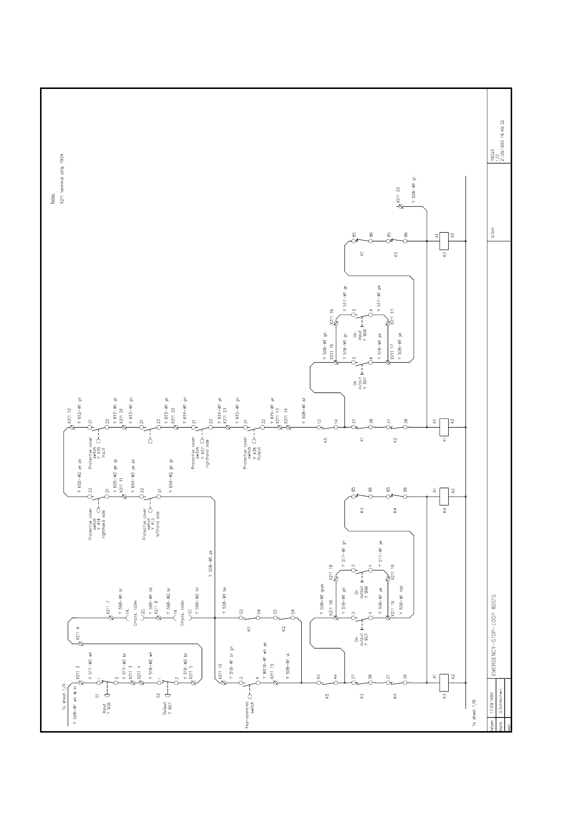
1.3 Safety Concept
The following pages include the circuit diagrams for the safety concept of SIPLACE machines.
–
2 circuit diagrams: 80S-15 emergency-stop circuit
–
2 circuit diagrams: 80F3 emergency-stop circuit
–
2 circuit diagrams: G emergency-stop circuit
1 Operational Safety SIPLACE 80 S/F/G Service Manual
Edition 04/97
1 - 12
Fig. 1.3.1 80S-15 emergency-stop circuit