80S-15贴片机.pdf - 第205页
SIPLACE 80 S/ F/G Service M anual 7 Components Table Edition 04/97 7 - 23 Fig. 7. 4.2 Replacing the flap opener (without cast iron strip) 7.4. 2.4 Adjusting the Flap Opener relative to the Components Table The fla p open…

7 Components Table SIPLACE 80 S/F/G Service Manual
Edition 04/97
7 - 22
●
Complete the SITEST program and switch the machine off at the main switch.
●
Disconnect the machine from the main power supply!
●
Remove the cover over the compressed air unit (2 special socket-head cap screws M3) and in addition
switch off the compressed air at the shut-off valve of the compressed air unit (see User’s Manual, Section
9).
●
Open the protective cover over the corresponding flap opener.
●
Replacing the screw-in cylinder:
●
Unscrew and remove the leaky or stiff screw-in cylinder (use an open-ended spanner, size SW7).
●
Lubricate the o-ring of the new screw-in cylinder with vaseline before fitting it and screw in the screw-
in cylinder as far as the stop (see Fig. 7.4.1).
●
Close the protective covers, connect the machine to the power supply, switch on the compressed air
at the compressed air unit, switch the machine on, load the SITEST program and make sure that the
flap opener functions correctly, as described above.
●
Replacing flap openers
●
Pull off the adhesive tape on the longer side of the cast iron strip.
●
Undo the compressed air connection at the quick-release coupling of the flap opener (on the left, see
Fig. 7.4.1) and unplug the plug connection (X38) at the flap opener board (on the left beneath the strip,
see Fig. 7.4.2)
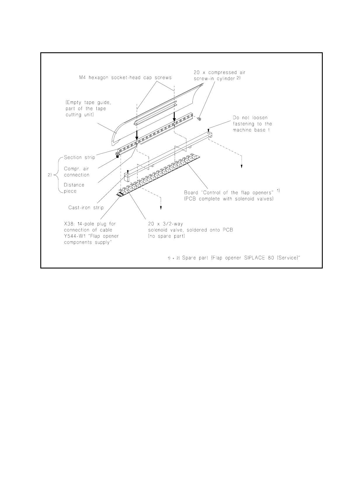
NOTE:
The "Flap opener control" board and the section strip with screw-in cylinders are only replaced together
(aligned unit = flap opener Siplace 80 Service).
Here the cast iron strip remains in position on the machine base. If it is removed you will need to align the
flap opener including cast iron strip to the components table when refitting it, as shown in Fig. 7.4.3, in
order to ensure the feeder modules are operating properly.
●
Undo the 2 socket-head cap screws M4 in the empty tape channel, remove the flap opener (see 1+2
in Fig. 7.4.2) from the cast iron strip, lifting the empty tape channel upwards and off.
●
Fit the new flap opener including empty tape channel to the cast iron strip (2 socket-head cap screws
M4).
●
Stick a new piece of Tesa adhesive tape to the longer side of the cast iron strip so that the board and
gap are covered over their entire width and length, as shown in Fig. 7.4.1.
●
Align the empty tape channel symmetrically with the pressure rod of the empty tape cutting device as
described in section 7.6 "Empty Tape Cutting Unit and Empty Tape Channel".
●
Close the protective covers, connect the machine to the power supply, switch on the compressed air
at the compressed air unit, switch on the machine at the main switch, check the 2.8 bar pressure.
●
Load the SITEST program and make sure the flap opener functions correctly, as described above.
●
Fit the cover over the compressed air unit, load the station software.
SIPLACE 80 S/F/G Service Manual 7 Components Table
Edition 04/97
7 - 23
Fig. 7.4.2 Replacing the flap opener (without cast iron strip)
7.4.2.4 Adjusting the Flap Opener relative to the Components Table
The flap opener must in the following cases be aligned with the components table:
–
In the event of a fault, as when the feeder modules are not being correctly operated despite other faults
being excluded, such as restricted movement of the screw-in cylinder (see Fig. 7.4.3) or incorrect adjust-
ment at the feeder module. This will express itself through a fault in components removal or in the tape
cycling (see User’s Manual "Feeder Modules").
–
After refitting the cast iron strip (including flap opener) to the machine base.
●
Adjust the flap opener as follows:
●
Loosen off the strip at little from the machine base (2 socket-head cap screws M6).
7 Components Table SIPLACE 80 S/F/G Service Manual
Edition 04/97
7 - 24
●
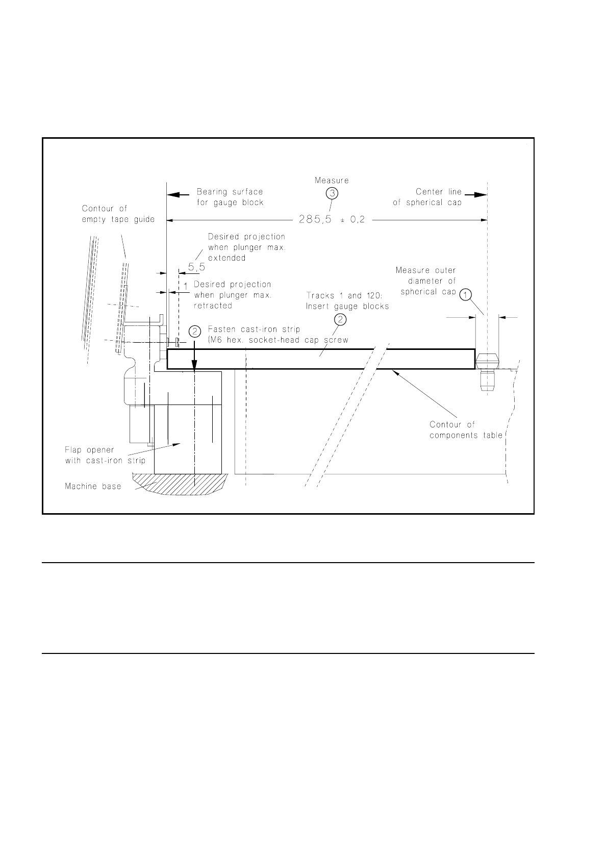
Undo the screws fastening the cast iron strip to the machine base (2 socket-head cap screws M6) and with
the aid of gauge blocks align the flap opener so that the dimension of 285.5
±
0.2 mm can be measured at
both track 1 and track 120. The procedure is shown in Fig. 7.4.3. Screw the strip down tight in this position.
Fig. 7.4.3 Aligning the flap opener including cast iron strip
NOTE:
After adjusting the flap opener you must not forget to align the empty tape cutting device (pressure rod) sym-
metrically with the empty tape channel (see section 7.6.14 "Fitting and Aligning the Empty Tape Cutting Unit
and Empty Tape Channel", under "Fitting and aligning the empty tape channel"). To do this, the components
changeover table has to be removed.