80S-15贴片机.pdf - 第347页
SIPLACE 80S/F/G Service Manual 9 Revolver Head Edition 04/97 9 - 63 The conver sion board "He ad" 1710 491-Y030 3 is the centr al board in the revolver head. It ca rries all pl ug con- nections for the ind ivid…
9 Revolver Head SIPLACE 80S/F/G Service Manual
Edition 04/97
9 - 62
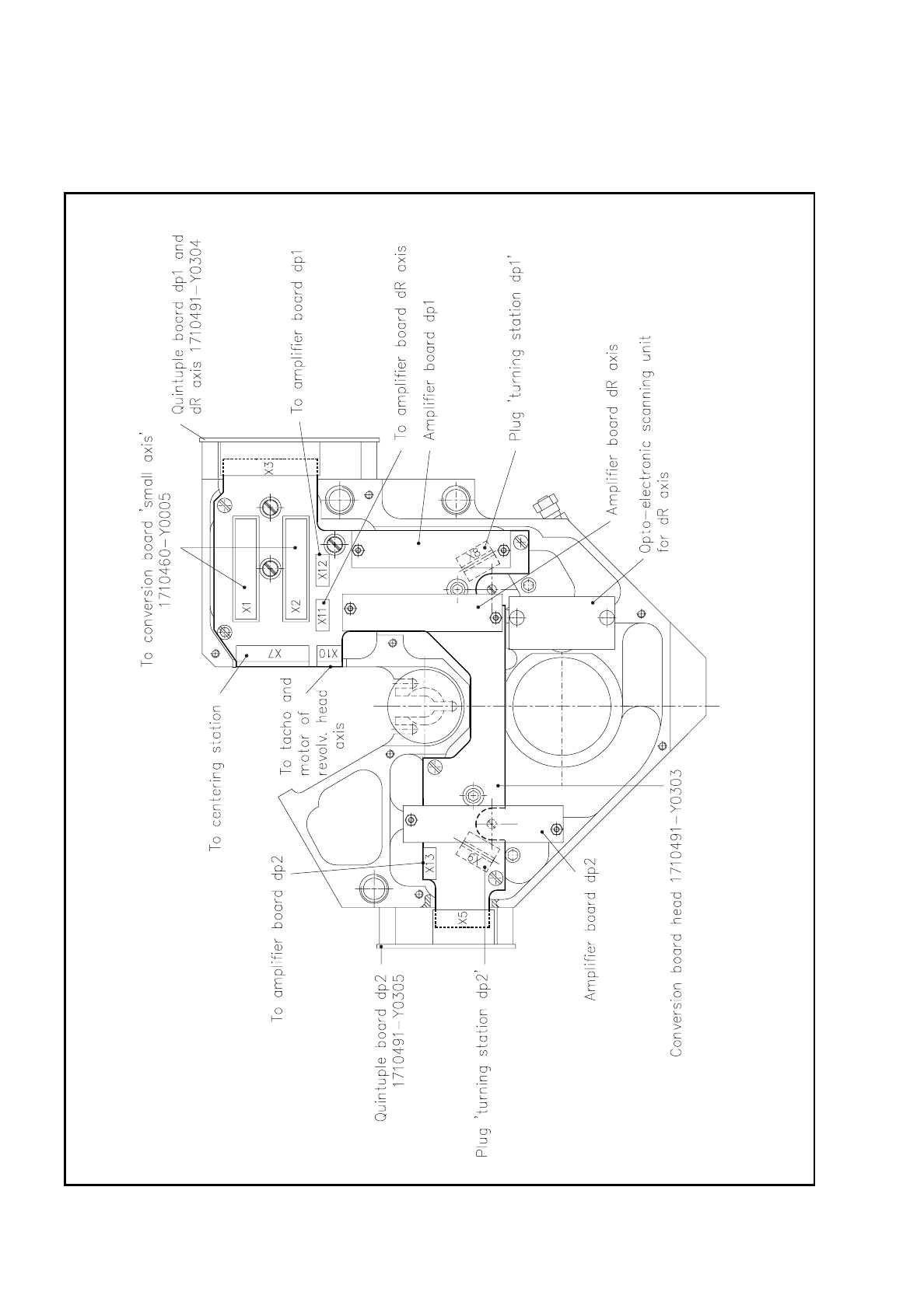
9.6.7 Conversion Board "Head" 1710491-Y0303
Fig. 9.6.14 Conversion board “Head“ - 1710491-Y0303

SIPLACE 80S/F/G Service Manual 9 Revolver Head
Edition 04/97
9 - 63
The conversion board "Head" 1710491-Y0303 is the central board in the revolver head. It carries all plug con-
nections for the individual function groups of the revolver head and is connected via plugs X1 and X2 with the
conversion board "Small axis" 1710460-Y0005. These connections run on to the conversion board "Gantry"
1710460-Y0003 and from there to the control and servo unit. The amplifier boards of the dp1, dp2 and dR
axes are also mounted on the conversion board "Head".
The following connections are made via the plugs on the conversion board "Head":
Plug X1 (26-pin) bero dp1
bero dp2
feed motor dp1
feed motor dp2
motor-tacho combination dp1 axis
motor-tacho combination dp2 axis
motor-tacho combination dR axis
voltage supply ± 5 V, 24 V
Plug X2 (26-pin) track signals A, A
, B, B and
zero pulse signals N, N
of the dp1, dp2 and dR axes
beros 1, 2 and 3 and
motor of the centering station
X3 (26-pin) quintuple board 1710491-Y0304 for conversion of the dp1 and dR axes analog track
signals to digital signals
board power supply
X5 (14-pin) quintuple board 1710491-Y0305 for conversion of the dp2 axis analog track signals to
digital signals
board power supply
X7 (11-pin) signals of beros 1, 2 and 3
motor of the centering stations
X8 (10-pin) bero dp1, feed motor
motor-tacho combination dp1
X9 (10-pin) bero dp2, feed motor
motor-tacho combination dp2
X10 (4-pin) motor-tacho combination dR axis
X11 (8-pin) track signal, zero pulse and power supply for the amplifier board of the dR axis
X12 (8-pin) track signals, zero pulse and power supply for the amplifier board of the dp1 axis
X13 (8-pin) track signals, zero pulse and power supply for the amplifier board of the dp2 axis

9 Revolver Head SIPLACE 80S/F/G Service Manual
Edition 04/97
9 - 64
9.6.8 Amplifier Boards for the dp1, dp2 and dR Axes
The amplifier boards for the dp1, dp2 and dR axes are fastened with spacer pins to the conversion board
"Head". These boards amplify the sinusoidal signals coming from opto-electronic scanner units. Each scanner
unit supplies five sinusoidal signals:
two for track A
two for track B (rotated by 90° with respect to track A)
one for the zero pulse
For each track the mean value is formed from the two arriving sinusoidal signals and conditioned for the quin-
tuple board. With the zero pulse no averaging takes place (see Fig. 9.6.15).
NOTE
The opto-electronic scanner unit and the amplifier board are set to one another in the factory and can there-
fore only be replaced as a unit. As a rule this unit will be replaced in the factory.
9.6.9 Quintuple Boards
The quintuple boards are located on the outside of the encoder housing by the conversion board "Head" (see
Fig. 9.6.14). Board 1710491-Y0304 converts the analog track and zero pulse signals coming from the ampli-
fier boards into digital pulses and quintuples, or multiplies them by five. It is connected via plug X3 to the con-
version board "Head".
Board 1710491-Y0305 converts the analog track and zero pulse signals coming from the amplifier boards into
digital pulses and quintuples them. It is connected by plug X5 to the conversion board "Head". Fig. 9.6.15
shows the signal processing which the track signals of the dp1, dp2 and dR axes undergo.