80S-15贴片机.pdf - 第434页
9 Revolver Head SIPLACE 80S/F/G Service Manual Edition 04/97 9 - 150 PLEASE N OTE: Note th e order of t he segment s and from wh ich star positio n you remo ved the segments. In this wa y, you will en sure tha t the c on…

SIPLACE 80S/F/G Service Manual 9 Revolver Head
Edition 04/97
9 - 149
9.20 Service work on the sz axis
9.20.1 Tools, equipment and consumables
9.20.2 Spare parts
9.20.3 Replacing the DC servo motor
DANGER
OOO
Switch the placement machine off at the main switch and disconnect from the power supply.
●
Remove all the segments using the appropriate segment changing device and place the segments in the
segment case.
From item number
Set of screwdrivers
Set of hexagon socket-head screwdrivers
Open-end spanner, size 10
Diagonal cutter
Hot air gun
0.15 mm feeler gauge
SIPLACE segment changing device, version I
00310699-01
SIPLACE segment changing device, version II
00305897-02
Segment case
00302217-01
Adjustment instructions
SITEST program
Circuit diagrams
Cable ties
Shrink-fit hose
From item number
DC servo motor 28 GTD 28 and incremental shaft encoder
00201299-01
Completely assembled cam
00201209-01
3 RG 4603 2AB00/3.0 mm/SN = 0.6 mm/1S BERO
00303945-01
9 Revolver Head SIPLACE 80S/F/G Service Manual
Edition 04/97
9 - 150
PLEASE NOTE:
Note the order of the segments and from which star position you removed the segments. In this way, you
will ensure that the configuration will be correct when you refit the segments.
●
Remove the cable ties and detach connector X15 on the ’Small axis’ conversion board Y0005 (see Fig.
9.12.1 on page 9 - 98).
●
Disconnect the motor and tacho cables from connector X1 (see items 3, 4, 5 and 6 in Fig. 9.20.2).
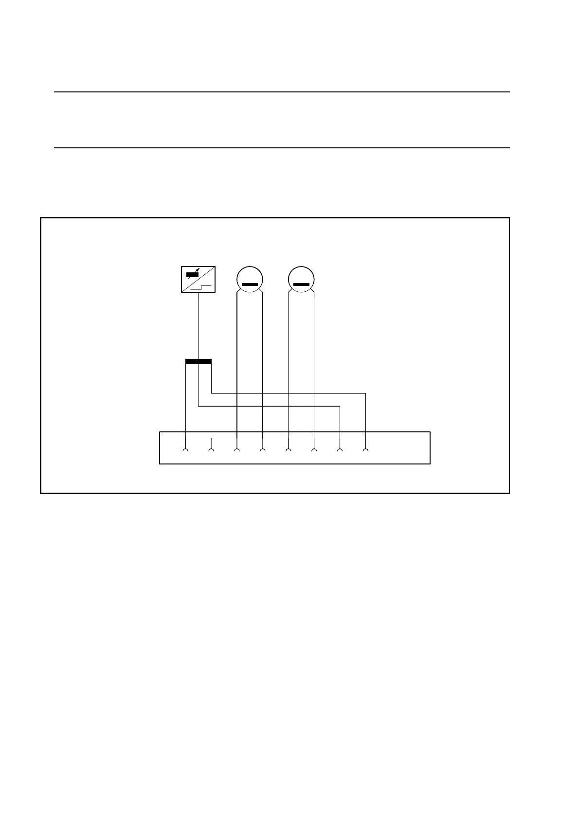
Fig. 9.20.1 Connector assignment for the DC motor and BERO of the sz axis
Key to Fig. 9.20.1
●
Dismantle the PCB camera (see items 1. 2, 3, 6 and 8 in Fig. 9.14.1 on page 9 - 108) and the cover (see
item 4 in Fig. 9.14.1 on page 9 - 108) as described in Section 9.14.2 on page 9 - 107.
3 Tacho connection: blue 1 BERO connection: black
4 Tacho connection: white 7 BERO connection: brown
5 Motor connection: black 8 BERO connection: blue
6 Motor connection: red X1 Connector for slot X15 on the
’Small axis’ conversion board Y0005
X1
+-
T
-+
M
21 345678
B1 Tacho Motor
SIPLACE 80S/F/G Service Manual 9 Revolver Head
Edition 04/97
9 - 151
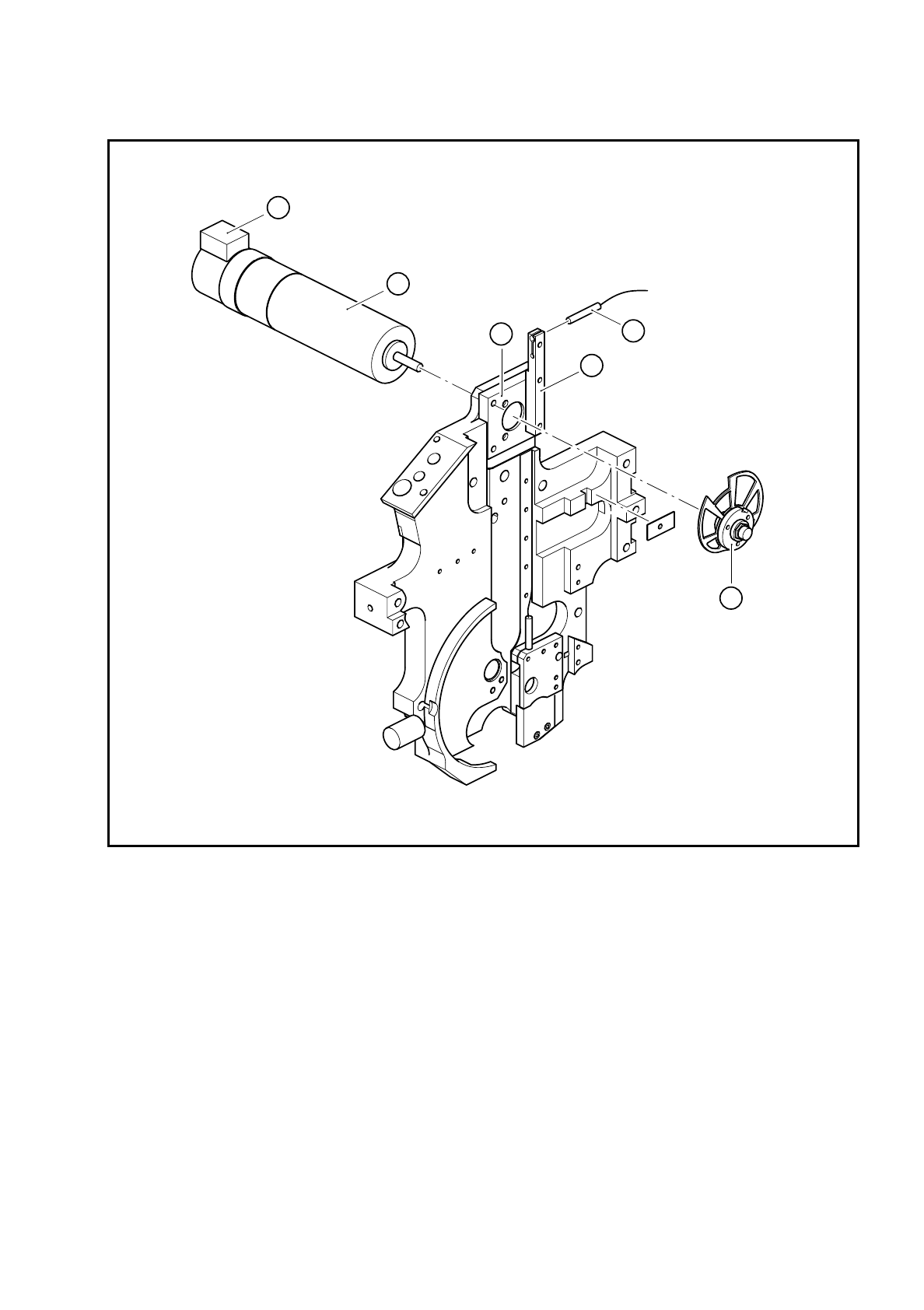
Fig. 9.20.2 Sz axis drive
Key to Fig. 9.20.2
●
Loosen the M6x0.5 hexagon nut for fixing the cam disk (see item 5 in Fig. 9.20.2).
●
Remove the cam disk.
●
Loosen the three M3x6 countersunk screws on the motor mount (see item 2 in Fig. 9.20.2).
●
Replace the DC servo motor (see item 1 in Fig. 9.20.2) and fix in place.
1 DC servo motor 28GDT12 and incremental shaft encoder
2 Motor mount
3 3RG4603 2AB00 BERO
4 BERO holder
5 Completely assembled cam
A The incremental shaft encoder points upwards
5
2
1
4
3
A