80S-15贴片机.pdf - 第222页
7 Components Table S IPLACE 80 S/F/G Servic e Manual Edition 04/97 7 - 40 Please note: The measu reme nt point mu st be a djace nt to the cu tter strip , the disp lay m ust now sh ow "0.0 mm". ● Unscr ew the th…

SIPLACE 80 S/F/G Service Manual 7 Components Table
Edition 04/97
7 - 39
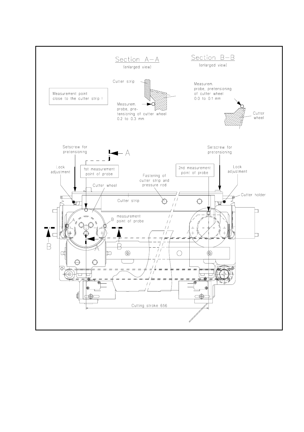
7.6.7 Checking and Adjusting the Inclination of the Cutter Wheel
–
To be measured on cutting units from item no.: 00313882-06 to 00315060-02
●
Disengage the tension springs of the cutter strip.
●
Fold the cutting blade towards the rear so that the cutter wheel is disengaged.
●
Place the magnetic holder with measuring probe on the left side of the guide rail and lower the measuring
probe onto the cutter wheel above point B, as shown in Fig. 7.6.2.
To be observed:
Measuring points A and B must be in a centered position and parallel with respect to the blade.
●
Move the cutter wheel so that the measuring probe is located above point A.
●
Set the measuring probe to the "0" position.
●
Now move the cutter wheel so that point B is positioned below the measuring probe.
The measured value should lie anywhere between 0.0 ... 0.1 mm.
●
Correct the adjustment at the slotted screw on the carriage (see Fig. 7.6.2).
7.6.8 Checking and Adjusting the Pretensioning of the Cutter Wheel
This check and adjustment should be carried out
–
if the tapes are not being cut properly (pretensioning of the cutter wheel is too low),
–
if stiffness has led to the motor switching out (pretensioning is too high),
–
if you have replaced the cutter wheel and the cutter strip.
NOTE:
The empty tape cutting unit can remain installed for the following work on the machine. However in this case
you must remove the strip including flap opener and empty tape channel in order to allow access to the setting
screws. Please note: after reinstallation the flap opener must be aligned with the spherical caps (see section
7.4 "Flap Opener (Magazine Openers)" and the empty tape channel adjusted symmetrically to the pressure
rod of the tape cutting unit (see corresponding section, below).
CAUTION
OO
Do not reach into the area of the cutter strip and cutter wheel:
danger of physical injury!
●
If the empty tape cutting unit has already been removed from the machine in the course of fault location,
set it down in a stable horizontal position, fastening it so that during the following work you can position the
magnetic holder with the measuring probe correctly on the guide rail.
●
Move the cutter wheel carriage to the lefthand end position:
●
Undo the locking of the lefthand and righthand thrust pieces in the cutter holder and screw the thrust
pieces in until the cutter strip rests against the cutter wheel without pretensioning.
●
Place the magnetic holder with measuring probe (for Item No., see "Auxiliary Measuring and Test
Equipment") on the left on the guide rail and lower the measuring probe onto the cutter wheel as
shown in Fig. 7.6.2.

7 Components Table SIPLACE 80 S/F/G Service Manual
Edition 04/97
7 - 40
Please note:
The measurement point must be adjacent to the cutter strip, the display must now show "0.0 mm".
●
Unscrew the thrust piece (lefthand) out of the cutter holder until the cutter wheel is pretensioned 0.2 to
0.3 mm by the cutter strip.
●
Move the cutter wheel carriage by hand into the righthand end position.
●
Move the magnetic holder on the guide rail to the right.
●
Place the measuring probe on the cutter wheel (see Fig. 7.6.2) and set it to "0".
●
Screw out the righthand thrust piece until the cutter wheel is pretensioned 0.2 to 0.3 mm.
●
Check the setting by repeating the first measurement (=lefthand). If necessary, correct again the preten-
sioning of the cutter wheel and lock both thrust pieces in this position.
●
Carry out a cutting test by
(caution! danger of physical injury from the blade!)
a large enough piece of
foil of a suitable thickness (approx. 0.2 mm) to the cutter strip and moving the cutter wheel slide by hand.
After just one cutting stroke the foil must have been cut and separated.
SIPLACE 80 S/F/G Service Manual 7 Components Table
Edition 04/97
7 - 41
Fig. 7.6.2 Checking and replacing the cutter strip and cutter wheel; adjusting the pretensioning