80S-15贴片机.pdf - 第436页
9 Revolver Head SIPLACE 80S/F/G Service Manual Edition 04/97 9 - 152 PLEASE N OTE: Posit ion the sz motor s o that t he increme ntal shaft encod er points up wards ( see poin t A in Fig. 9.20 .2). ● Fix the cam d isk on …
SIPLACE 80S/F/G Service Manual 9 Revolver Head
Edition 04/97
9 - 151
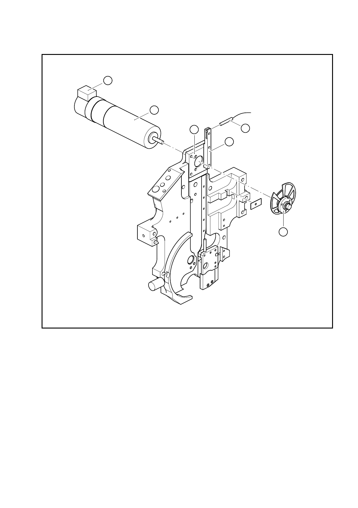
Fig. 9.20.2 Sz axis drive
Key to Fig. 9.20.2
●
Loosen the M6x0.5 hexagon nut for fixing the cam disk (see item 5 in Fig. 9.20.2).
●
Remove the cam disk.
●
Loosen the three M3x6 countersunk screws on the motor mount (see item 2 in Fig. 9.20.2).
●
Replace the DC servo motor (see item 1 in Fig. 9.20.2) and fix in place.
1 DC servo motor 28GDT12 and incremental shaft encoder
2 Motor mount
3 3RG4603 2AB00 BERO
4 BERO holder
5 Completely assembled cam
A The incremental shaft encoder points upwards
5
2
1
4
3
A

9 Revolver Head SIPLACE 80S/F/G Service Manual
Edition 04/97
9 - 152
PLEASE NOTE:
Position the sz motor so that the incremental shaft encoder points upwards (see point A in Fig. 9.20.2).
●
Fix the cam disk on the motor shaft.
●
Wire up the motor as shown in the wiring diagram in Fig. 9.20.1.
●
After assembly, check the dynamic behavior and functioning of the sz axis with reference to the adjust-
ment instructions and using the SITEST program.
9.20.4 Replacing the cam disk
Dismantling and assembly of the cam disk are described in Section 9.20.4 on page 9 - 152.
●
After assembly, check the dynamic behavior and functioning of the sz axis with reference to the adjust-
ment instructions and using the SITEST program.
9.20.5 Replacing the BERO of the sz axis
●
Loosen the clamping screw on the BERO holder (see item 4 in Fig. 9.20.2).
●
Replace the BERO.
The electrical connections are shown in Fig. 9.20.1.
●
Use a 0.15 mm feeler gauge to adjust the operating distance of the BERO for the sz axis.
●
Then check the functioning of the BERO using the SITEST program.
SIPLACE 80S/F/G Service Manual 9 Revolver Head
Edition 04/97
9 - 153
9.21 Service work on the vacuum system
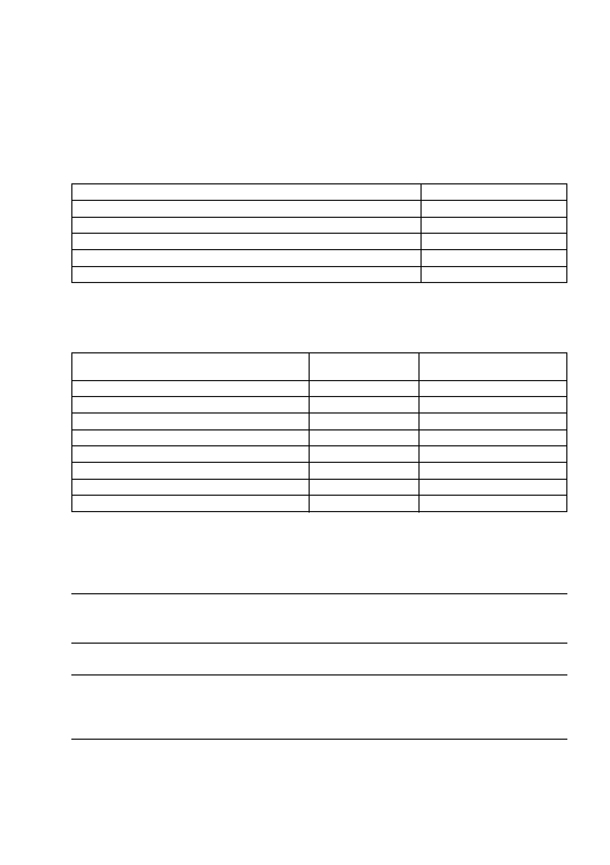
9.21.1 Tools, equipment and consumables
9.21.2 Spare parts
9.21.3 Replacing the vacuum measurement board Y0007
DANGER
OOO
Switch the placement machine off at the main switch and disconnect from the power supply.
WARNING
OO
Switch the compressed air supply off at the stop valve on the compressed air unit and wait until the lines have
depressurized.
●
Disconnect the broad-band cable from the plug on the vacuum measurement board.
●
Disconnect the vacuum hoses from the vacuum measuring tubes on the vacuum measurement board (see
item 3 in Fig. 9.21.1).
From item number
Set of screwdrivers
SIPLACE segment changing device, version I
00310699-01
SIPLACE segment changing device, version II
00305897-02
Segment case
00302217-01
Housing retainer
00306798-01
Number in
Fig. 9.21.1.
From item number
Throughput nozzle silencer
1 00323534S01
Vacuum measurement board Y0007
3 00300222S03
Vacuum nozzle, complete
5 00313251S01
O-ring, 6x1, NBR 75B
6 00201180-01
O-ring, 8x1, NBR 70B
7 00201179-01
Distributor
8 00306613-03
O-ring, 9x1, NBR 70B
9 00201383S01
O-ring, 4x1.2, NBR 70B
10 00303110S01