80S-15贴片机.pdf - 第218页
7 Components Table S IPLACE 80 S/F/G Servic e Manual Edition 04/97 7 - 36 ● Check the firm se ating or good cont act – of the pl ug con nection X 3ak (see F ig. 7.6.1 ) on th e undersid e of the tape cutti ng unit , – of…

SIPLACE 80 S/F/G Service Manual 7 Components Table
Edition 04/97
7 - 35
Sec.9).
●
Check the pretensioning of the cutter wheel (see the section which follows).
●
If necessary, correct the toothed belt tension of the cut and endless toothed belt
(see Section below).
–
No motor activation, but the pressure rod swings into position (= solenoid valve switches):
●
The motor is defective or there is an interruption between the motor and the plug X3ak at the tape
cutting unit
–
No motor activation and the pressure rod does not swing into position (= solenoid valve is not switch-
ing):
●
Check the plug connections, the limit switches and the cable Y637/Y638, as described below.
–
Motor activation, but the pressure rod does not swing in:
●
Check the wiring of the valve and compressed air circuit; if necessary, replace the solenoid valve.
–
After the motor has switched out: pressure rod does not swing out: the solenoid valve is defective
(does not return to initial position).
7.6.2.2 Checking the Limit Switch and Cable Y637, Y638
●
"Abort placement" has already been selected (see above).
GEFAHR
QQQ
Switch off the machine at the main switch and disconnect it from the power supply.
●
Removing the components changeover table:
●
Undo the plug connections of the components changeover table at the machine base on the right of
the components changeover table (mains plug and interface connector X37, and, if applicable, the
pneumatics connection).
●
Open the protective covers and lift the cover at the components loading point upwards and out. Slide
the placement head by hand over the board conveyor. Please read the CAUTION note in section 7.2
"Fault Characteristics".
●
Cut off the empty tapes - if they have not already been cut - at the front end of the module (= outside).
●
Release the tape retainer and use a lift truck to lift and move the components changeover table (including
any feeder modules being used) carefully out of the machine as described in the User’s Manual.
●
The empty tape cutting unit remains installed in the machine for the following work.
CAUTION:
OO
Do not reach into the area of the cutter strip and cutter wheel: danger of physical injury!
7 Components Table SIPLACE 80 S/F/G Service Manual
Edition 04/97
7 - 36
●
Check the firm seating or good contact
–
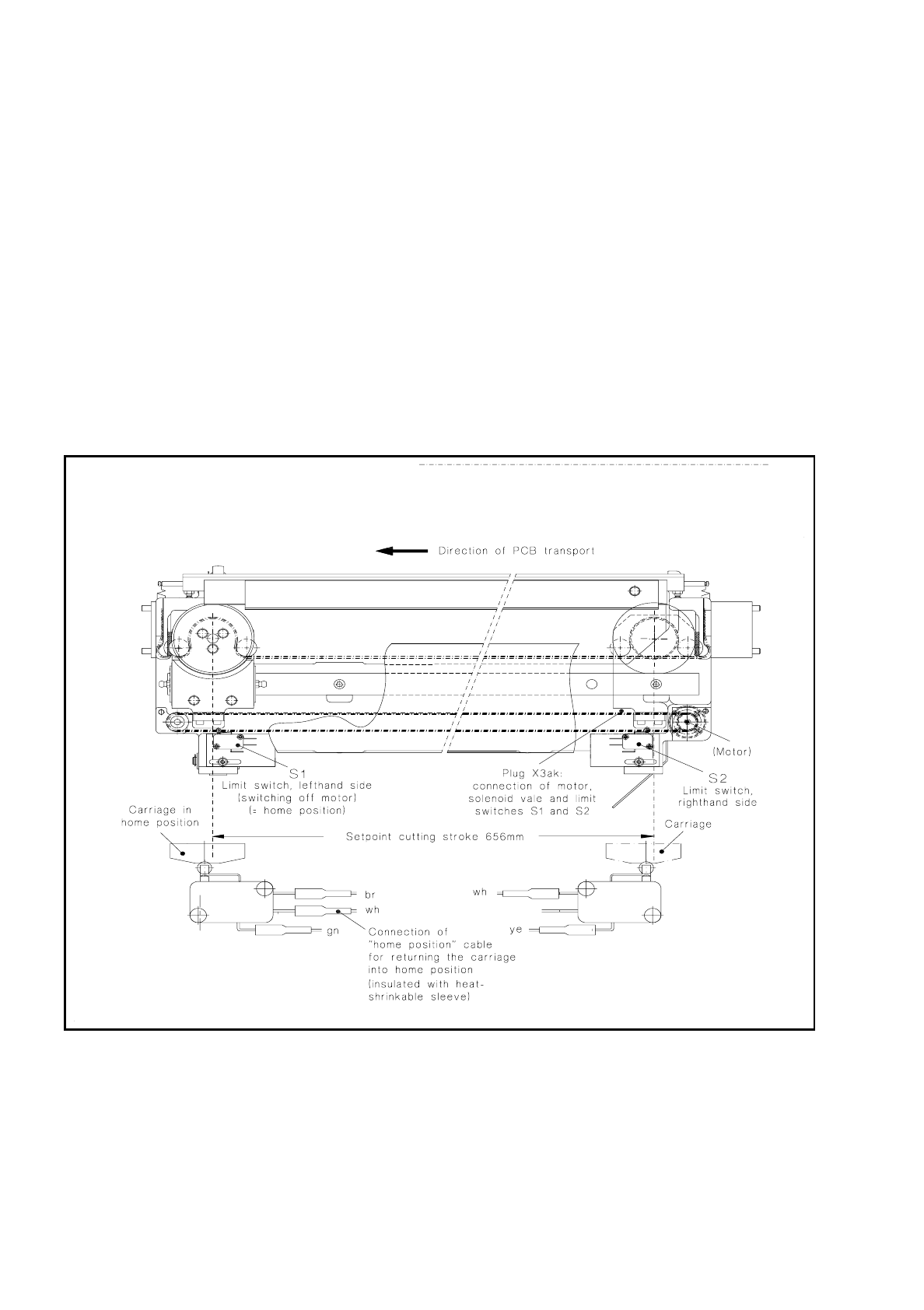
of the plug connection X3ak (see Fig. 7.6.1) on the underside of the tape cutting unit,
–
of the push-on receptacles at the d.c. motor (see Fig. 7.6.3),
–
of the push-on receptacles at the limit switches S1 and S2 (see Fig. 7.6.1),
–
of the 14-pin plug at the "Flap opener control" board. The plug is located on the left beneath the strip
(see Fig. 7.1.3 in section 7.1 "Overview").
●
Check the limit switches S1 and S2 (see Fig. 7.6.1):
●
Pull the push-on receptacles off the lefthand (S1) or righthand (S2) limit switch and connect the ohm-
meter to the limit switch (see diagram 1710470-Y0441/Y0442-..-L-..).
●
Move the cutter wheel slide (caution:
danger of injuring yourself on the cutter strip!
) by hand into
the corresponding end position - lefthand or righthand.
●
If the limit switch does not respond, or if there is a short circuit, replace the limit switch as described in
section 7.6.4 "Replacing the Lefthand or Righthand Limit Switch".
Fig. 7.6.1 Checking the plug connection X3ak and the righthand and lefthand limit switches
●
Check the cables Y637-W1/W2 and Y638-(see circuit diagram 1710460-Y0637-..-L-.. and 1710460-
Y0638-..L..).:
–
No break: continue with section 7.6.9 "D.C. Motor".
–
Cable break: replace the complete cable Y637 or cable Y638 as described in the next section.

SIPLACE 80 S/F/G Service Manual 7 Components Table
Edition 04/97
7 - 37
7.6.3 Replacing Cables Y637 and Y638
●
Pull out plug X3ak on the underside of the tape cutting unit and remove the cover from the cable duct.
Undo the cable lacings. Pull off the push-on sleeves (there may be a soldered connection, see Fig. 7.6.3)
at the motor and limit switches and disconnect the wiring at the solenoid valve (see Fig. 7.6.7).
●
Connect the new cable Y637 making sure the polarity is correct (diagram 1710460-Y0637-...-L- ..
or ..-Y0638-..).
●
The connection of the ceramic capacitor at the motor (push-on or soldered) is shown in Fig. 7.6.3. The
spare cable Y637 is inclusive of ceramic capacitor.
●
Removal of cable Y638: pull off the push-on sleeve from the "lefthand limit switch" and undo the socket-
head cap screw on the underside of the support.
●
Restore all cable lacings to their previous position. Note that the connections must not be under tensile
stress. Refit the cable duct cover.
●
Reconnect the plug connection X3ak.
●
Carry out the "Concluding work" as described at the end of this section.
7.6.4 Replacing the Lefthand or Righthand Limit Switch
CAUTION
OO
Do not reach into the area of the cutter strip and cutter wheel:
danger of physical injury!
●
The components changeover table has already been removed from the machine in the course of fault
location (see above).
●
Pull the push-on receptacles off the defective limit switch and undo the screws retaining the limit switch
(2 socket-head cap screws M3).
●
First screw the new limit switch up only a little and push on the push-on receptacles making sure that the
polarity of the wires is correct (see Fig. 7.6.1).
●
Adjust the cutting stroke by correcting the limit switch position, as described below.
7.6.5 Checking and Setting the Cutting Stroke
Check the cutting stroke (see Fig. 7.6.1) if the tapes of the outside tracks (1/120) are not being cut properly or
the limit switches have been replaced.
●
If you have not already done so, select now from within the track error menu "Abort placement".
●
Switch the machine off at the main switch and remove the components changeover table as described
above in the section 7.6.2.2 "Checking the Limit Switch and Cable Y637, Y638". Pay attention to the place-
ment head!
●
Move the slide by hand as far as the switching point (= audible click) of the lefthand limit switch. Now place
a rule in position, move the slide as far as the righthand switching point (= audible click) and check the cut-
ting stroke against the rule.