80S-15贴片机.pdf - 第384页
9 Revolver Head SIPLACE 80S/F/G Service M anual Edition 04/97 9 - 100 Fig. 9.12.2 Com pressed air lines on the vacuum generator block Key to Fig . 9.12.2 1 V acuum ge nerator block 2 Quick- releas e coupl ings f or the c…

SIPLACE 80S/F/G Service Manual 9 Revolver Head
Edition 04/97
9 - 99
●
Remove the cable ties and detach the following connectors
X9 X10 X13 X15 X17 X18
X22X20X23X24X25X27
from board Y0005 (see Fig. 9.12.1 on page 9 - 98)
PLEASE NOTE:
If a mechanical centering station is installed, detach the measuring cable from the CRDL measurement
board.
●
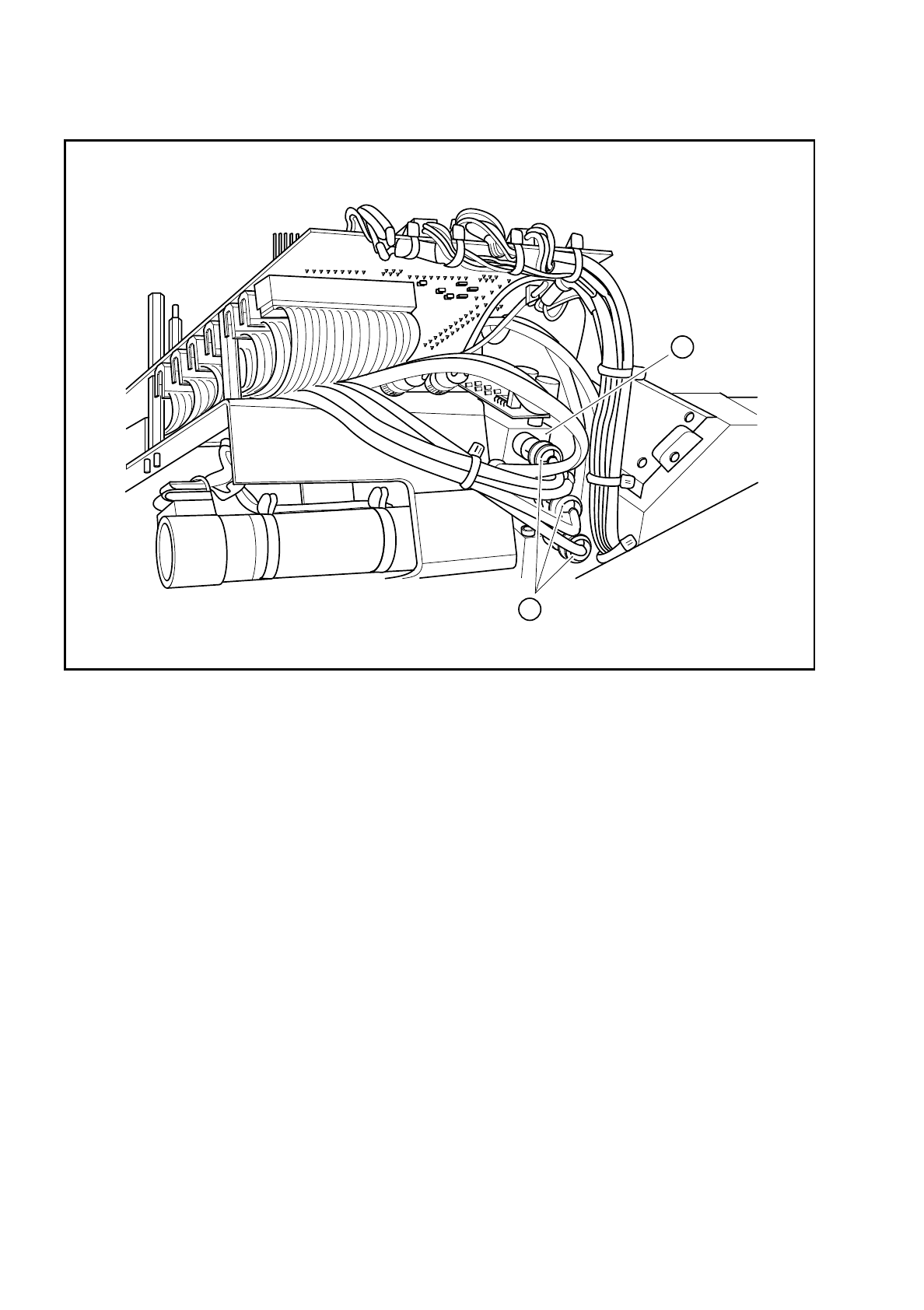
Detach the four compressed air lines from the vacuum generator block (see Fig. 9.12.2 on page 9 - 100)
●
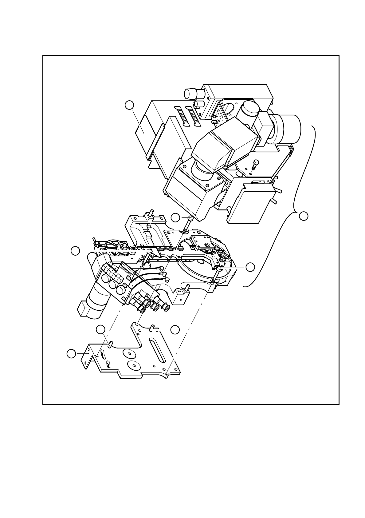
Loosen the two hexagon socket-head screws for fixing the cover (point 1 in Fig. 9.12.3 on page 9 - 102)
and remove the cover.
●
Loosen the three M3 hexagon socket-head screws for fixing the revolver head to the gantry (see item 2 in
Fig. 9.12.3).
●
Carefully lift the placement head (see item 3 in Fig. 9.12.3) away from the parallel pins (see item 4 in Fig.
9.12.3) of the head support on the gantry (see item 5 in Fig. 9.13.1). Then remove the head from the place-
ment system.
X15 Cable - ’Motor/tacho/BERO z axis’
X16 Cable - ’z axis track’
X17 Cable - ’Screwdriver 2’
X18 Cable - ’Screwdriver 1’
X20 Cable - ’Forced air valve, placement circuit’
X21 Cable - ’Track signals, X axis’
X22 Cable - ’Illumination control, PCB camera’
X23 Cable - ’PCB camera’
X24 Cable - ’Illumination control, component camera’
X25 Cable - ’Component camera’
X26 Cable - ’BERO end position, X axis’
X27 Cable - ’Forced air valve, reject circuit’
9 Revolver Head SIPLACE 80S/F/G Service Manual
Edition 04/97
9 - 100
Fig. 9.12.2 Compressed air lines on the vacuum generator block
Key to Fig. 9.12.2
1 Vacuum generator block 2 Quick-release couplings for the compressed air lines
1
2
SIPLACE 80S/F/G Service Manual 9 Revolver Head
Edition 04/97
9 - 101
Fig. 9.12.3 Fitting the revolver head to the head support on the gantry
Key to Fig. 9.12.3
1 Cover 4 Parallel pins
2 M3 hexagon socket-head screw 5 Head support on the gantry
3 Placement head
1
2
5
4
4
2
2
3