80S-15贴片机.pdf - 第423页
SIPLACE 80S/F/G Service Manual 9 Revolver Head Edition 04/97 9 - 139 9.18.7 Replacing the segment claw ● Loosen t he M 1.6 x 4 fill ister he ad scr ews on the cable bracket ( see item 1 in Fig . 9.18.6 ). ● Loosen t he M…
9 Revolver Head SIPLACE 80S/F/G Service Manual
Edition 04/97
9 - 138
●
Solder the connecting wires of the new BERO to the cut cable ends of the old BERO.
●
Carefully pull the new cable with the old cable through the cable duct in the lifting carriage.
●
Solder the connecting wires of the new BERO to conversion board Y0307 as shown in Fig. 9.18.4.
●
Place the BERO in the hole.
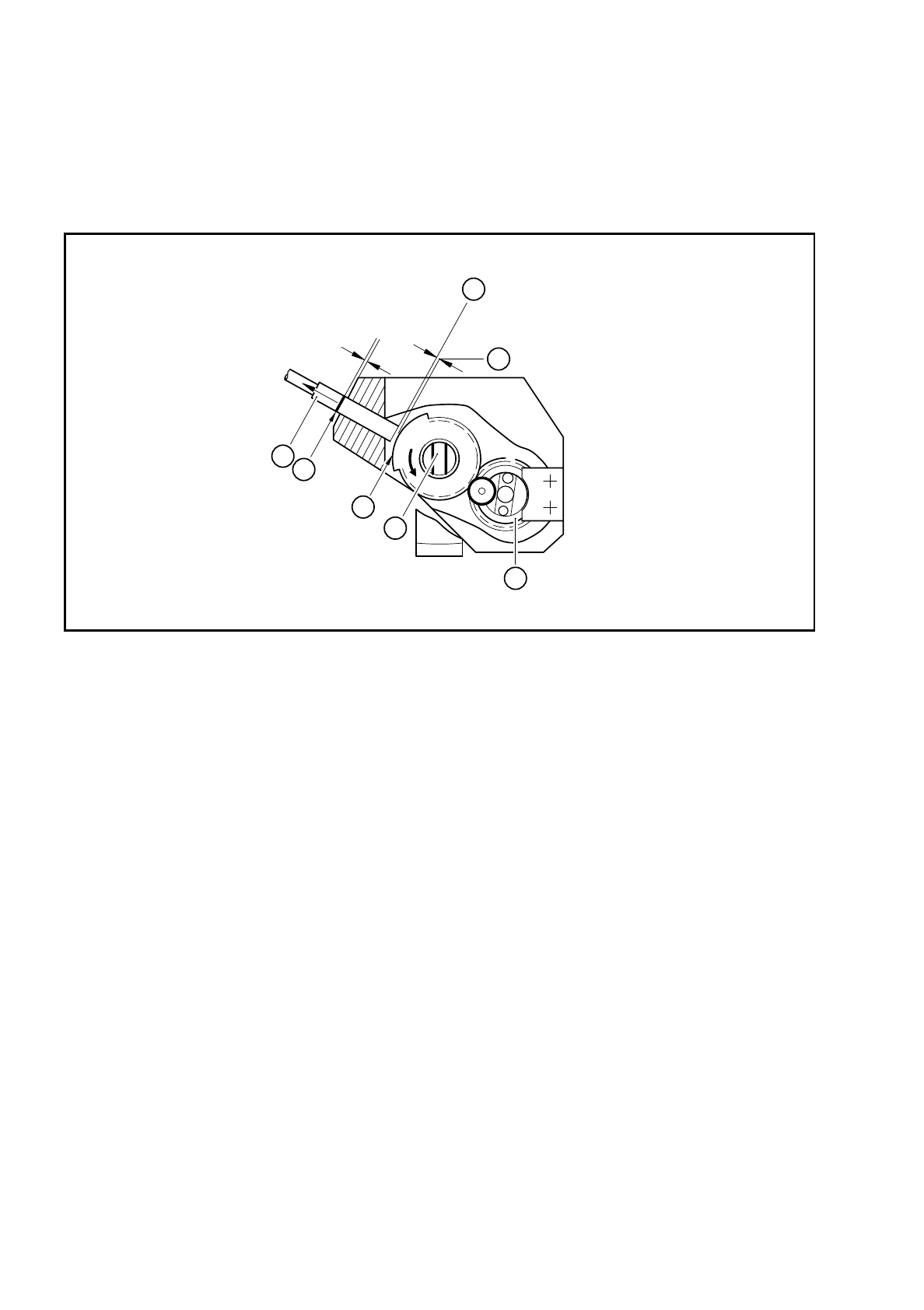
Fig. 9.18.5 Setting the BERO operating distance for screwdriver 1
Key to Fig. 9.18.5
●
Set the BERO operating distance.
–
Turn toothed wheel 1 (see item 4 in Fig. 9.18.5) until the screwdriver blade (see item 5 in Fig. 9.18.5)
is vertical.
–
Push the BERO (item 1 in Fig. 9.18.5) in until it touches the trigger surface (see item 3 in Fig. 9.18.5).
–
Use the scribing iron to carefully mark the BERO.
–
Pull the BERO back slightly and use a feeler gauge to measure a distance of 0.2 mm.
–
Clamp the BERO in this position.
–
When assembling the head, make sure that the screwdriver blade is horizontal. If it is not horizontal,
the star will not be able to turn the segments after assembly (see item 2 in Fig. 9.18.2).
●
After assembly, check the functioning of screwdriver with reference to the adjustment instructions and
using the SITEST program.
1 BERO 5 Screwdriver blade
2 Mark on the BERO made with the scribing iron 6 Operating distance 0.2 mm
3 Trigger surface of the toothed wheel 7 BERO trigger surface
4 Toothed wheel 1
3
0,2mm
0,2mm
7
6
4
5
2
1
SIPLACE 80S/F/G Service Manual 9 Revolver Head
Edition 04/97
9 - 139
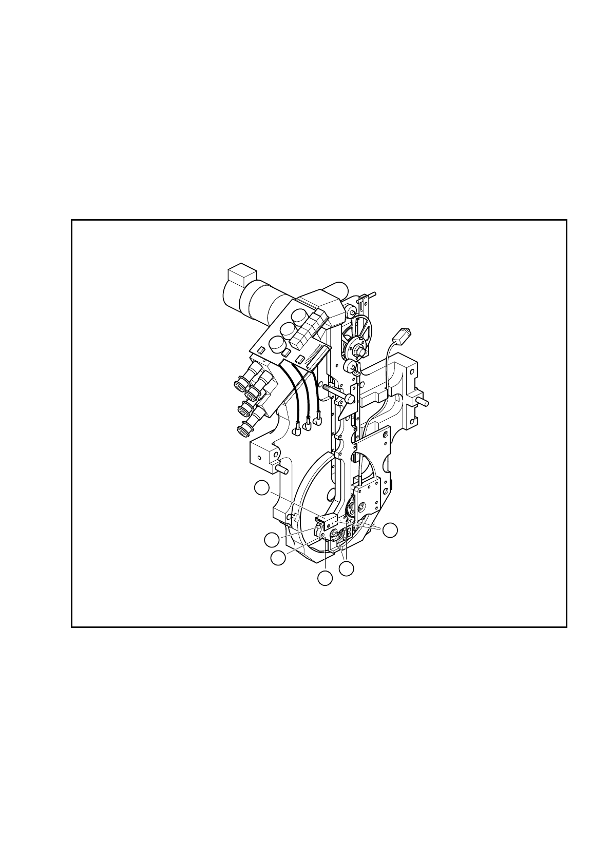
9.18.7 Replacing the segment claw
●
Loosen the M 1.6 x 4 fillister head screws on the cable bracket (see item 1 in Fig. 9.18.6).
●
Loosen the M 1.6 x 4 fillister head screws (see item 3 in Fig. 9.18.6) for clamping the BERO.
●
Pull the BERO out of the hole.
●
Loosen the two M 1.6 x 4 fillister head screws (see item 5 in Fig. 9.18.6) for fixing the segment claw.
●
Pull the segment claw carefully away from the parallel pins (see item 6 in Fig. 9.18.6).
●
Lightly grease the teeth of toothed wheel 1 (see item 4 in Fig. 9.18.5) with Unimoly GL82
Fig. 9.18.6 Replacing the segment claw
Key to Fig. 9.18.6
1 Cable bracket
2BERO
3 M 1.6 x 4 fillister head screws for clamping the BERO
4 Segment claw
5 M 1.6 x 4 fillister head screws for fixing the segment claw
6 Parallel pin for positioning the segment claw
6
4
3
2
1
5

9 Revolver Head SIPLACE 80S/F/G Service Manual
Edition 04/97
9 - 140
●
Insert the new segment claw.
●
Align the screwdriver blade with respect to toothed wheel 1 as shown in Fig. 9.12.2.
●
Fix the segment claw.
●
Insert the BERO and set the operating distance of 0.2 mm as shown in Fig. 9.18.5.
●
Fix the cable bracket.
●
Ensure that the screwdriver blade is horizontal when you assemble the head. If it is not horizontal, the star
will not be able to turn the segments after assembly.
●
Check the functioning of screwdriver 1 with reference to the adjustment instructions and using the SITEST
program.