Xg系列调整手册.pdf - 第22页
2 Before beginning adjustments 2- 16 2. Prepar atory w ork 2.6 Changing the machine setting (when needed during adjustment) When the machine setting needs to be changed during adjustments, you must exit the adjustment ut…
2
Before beginning adjustments
2-15
2. Preparatory work
2
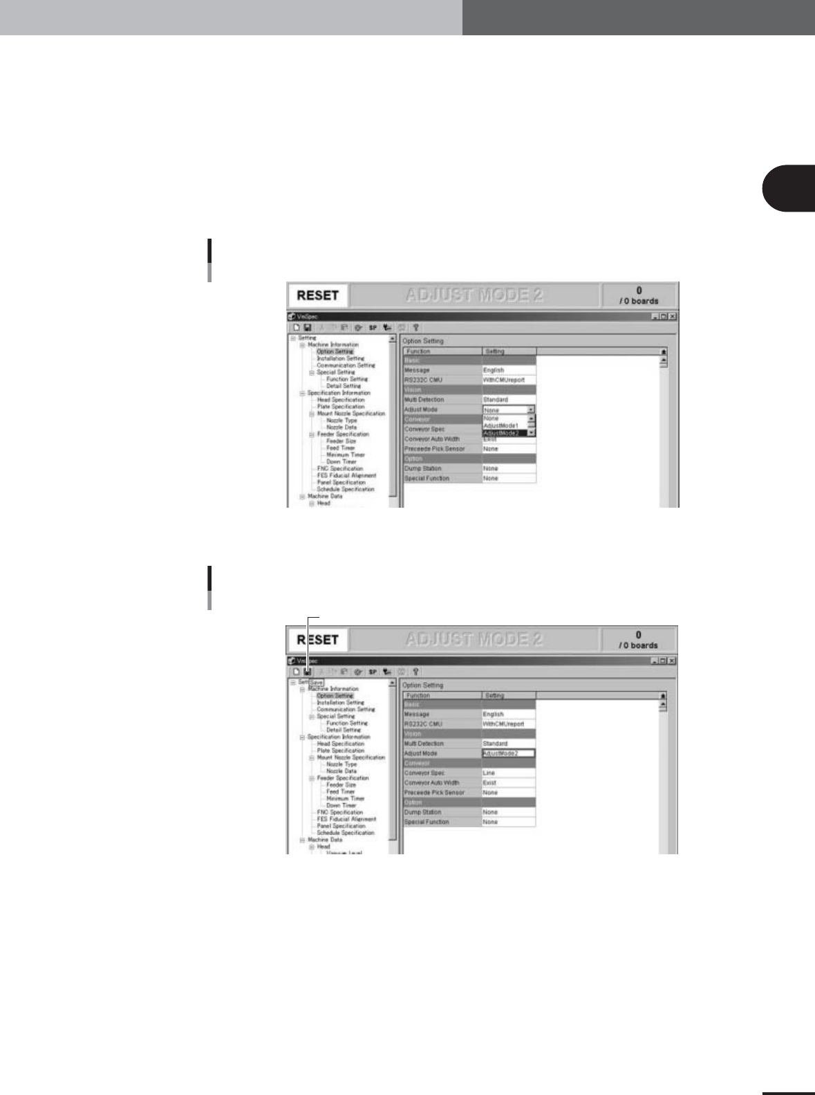
On the "Option Setting" screen, change the "Adjust Mode"
parameter as needed.
1.Check that "Option Setting" under "Machine Information" is selected in the left-
hand tree view and the "Option Setting" screen is displayed in the right-hand main
view.
2.Set the "Adjust Mode" parameter under "Vision" to match the adjustment work as
follows.
When using glass QFP: Set to "Adjust Mode2".
When using ceramic chip components: Set to "Adjust Mode1".
When using SOP: Set to "None".
Adjust Mode parameter
27022-X9-A0
3
Press the [Save] button on the toolbar to save the change.
[Save] button
[Save] button
27023-X9-00
2
Before beginning adjustments
2-16
2. Preparatory work
2.6 Changing the machine setting (when needed during
adjustment)
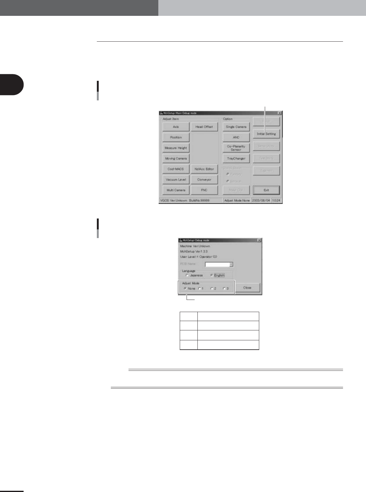
When the machine setting needs to be changed during adjustments, you must exit the
adjustment utility. However, only the "Adjust Mode" parameter can be changed while
you are still in the adjustment utility. To do this, press the [Initial Setting] button in the
adjustment utility menu window and select the "Adjust Mode" option buttons as needed.
Adjustment utility menu window
Press the [Initial Setting] button.
27021-X9-A0
Initial setting dialog box
None
1
2
3
Adjust Mode is not used.
Adjust Mode1
Adjust Mode2
Adjust Mode3
Select "Adjust Mode".
27200-X9-00
n
NOTE
The [Initial Setting] button in the adjustment utility menu window allows you to easily change the "Adjust Mode"
parameter without exiting the adjustment utility.
2
Before beginning adjustments
2-17
2. Preparatory work
2.7 Selecting the PCB data
To perform basic adjustments (explained in Chapter 3), the PCB data named
"MCH_SETUP" must be used.
To perform FAMF adjustments (explained in Chapter 4) after all necessary basic adjust-
ments are complete, the PCB data with a name beginning with "FAMF" must be used.
Be sure to load the specified PCB data into the machine to perform each adjustment
correctly.
PCB data used for machine adjustments
Adjustment items
Basic adjustments
Camera parameters
R-axis accuracy offset
Head offset
FAMF adjustments
(using glass PCB)
FAMF adjustments
(using adjustment station)
PCB data to be used Machine models
MCH_SETUP
FAMF_71_OLD
FAMF_72_OLD
FAMF_74_OLD
FAMF_61_OLD
FAMF_62_OLD
FAMF_64_OLD
FAMFST_73
FAMFST_74
FAMFST_63
FAMFST_64
FAMFST_65
YV100Xg family
YV88Xg
YV100Xg family
YV88Xg
YV100Xg family
YV88Xg
25017-X9-00
1
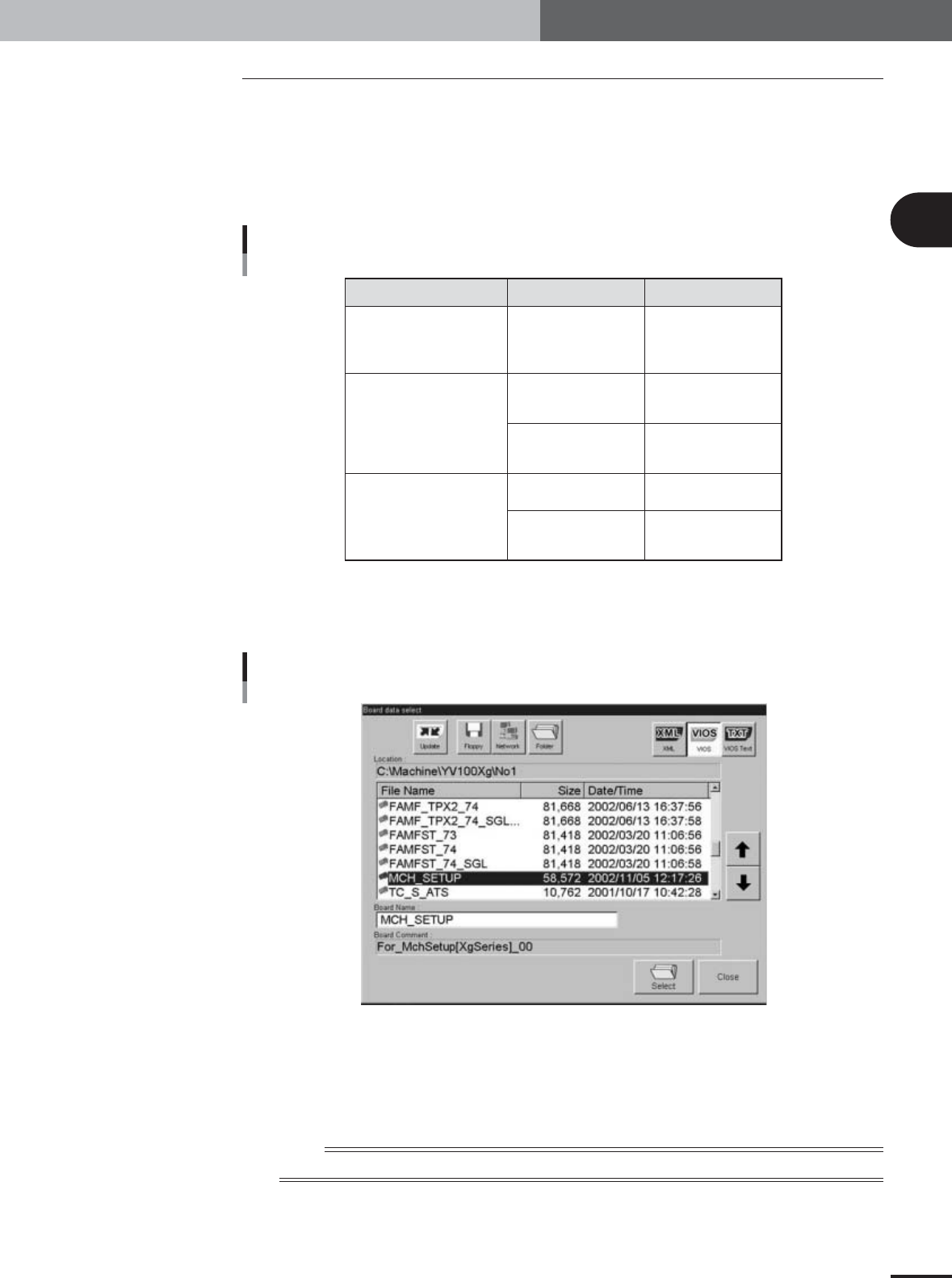
Press the [Board] button on the Setup screen.
The "Board data select" dialog box appears showing a list of registered PCB data.
Board Data Select dialog box
27024-X9-00
2
Select the PCB data.
1.Check that the [VIOS] button is pressed.
2.Line up the cursor with the PCB data you want to select and press the [OK]
button.
n
NOTE
Changes you made on the machine setting screen (VmSpec screen) are enabled after loading PCB data.