Xg系列调整手册.pdf - 第55页
3 Basic adjustments 3- 33 2. R-axis accur acy offset 3 Select the "R accuracy" option button under "Adjust Item". Selecting "R accuracy" Select "R accuracy" option button. 27100-X9…
3
Basic adjustments
3-32
2. R-axis accuracy offset
R-axis accuracy offset is the angular offset of the R-axis that rotates each nozzle shaft to
mount a component. This section explains how to measure R-axis accuracy offset with
the multi-vision camera and single-vision camera (option). The same glass QFP as for
camera scale calibration is used.
When measuring the R-axis accuracy offset of Heads 3, 5 and 7 (YV100Xg family), an
error occurs unless head offset adjustments have been performed on those heads. So,
before measuring the R-axis offset, perform head offset adjustments on Heads 3, 5 and 7
by referring to sections 3.1 and 3.2 in this chapter. In addition, when using SOP compo-
nents to measure the R-axis offset of Heads 2, 4, 6 and 8, also first perform head offset
adjustments on those heads by referring to sections 3.3 and 3.4 in this chapter.
c
CAUTION
Head offset adjustments performed before measuring the R-axis accuracy offset are temporary
settings. Be sure to perform head offset adjustments on all heads after the R-axis accuracy
offset measurements are complete.
n
NOTE
When measuring the R-axis accuracy offset of Heads 3, 5 and 7, a glass QFP is used so the "Adjust Mode" must
be set to "Adjust Mode2" (see sections 2.5 and 2.6 in Chapter 2). When measuring the R-axis accuracy offset of
Heads 2, 4, 6 and 8, SOP components are used so the "Adjust Mode" must be set to "None". In both cases, the
PCB data called "MCH_SETUP" must be loaded into the machine (see section 2.7 in Chapter 2). You can check
the currently selected PCB data and "Adjust Mode" displayed on the status bar.
2.1 Measuring the R-axis accuracy offset with the multi-vision camera
1
Press the [Utilities] button to start the adjustment utility.
n
NOTE
For how to start the adjustment utility, see section 2.4 in Chapter 2.
2
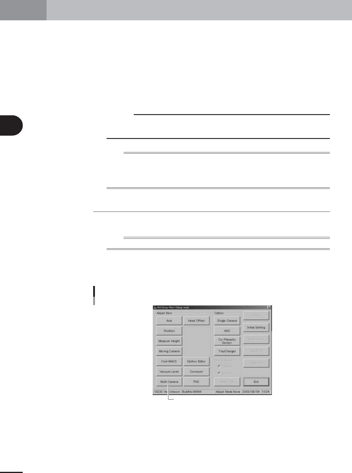
Press the [Multi Camera] button in the adjustment utility menu
window.
The multi-vision camera adjustment dialog box appears.
Adjustment utility menu window
[Multi Camera] button
27021-X9-F0
3
Basic adjustments
3-33
2. R-axis accuracy offset
3
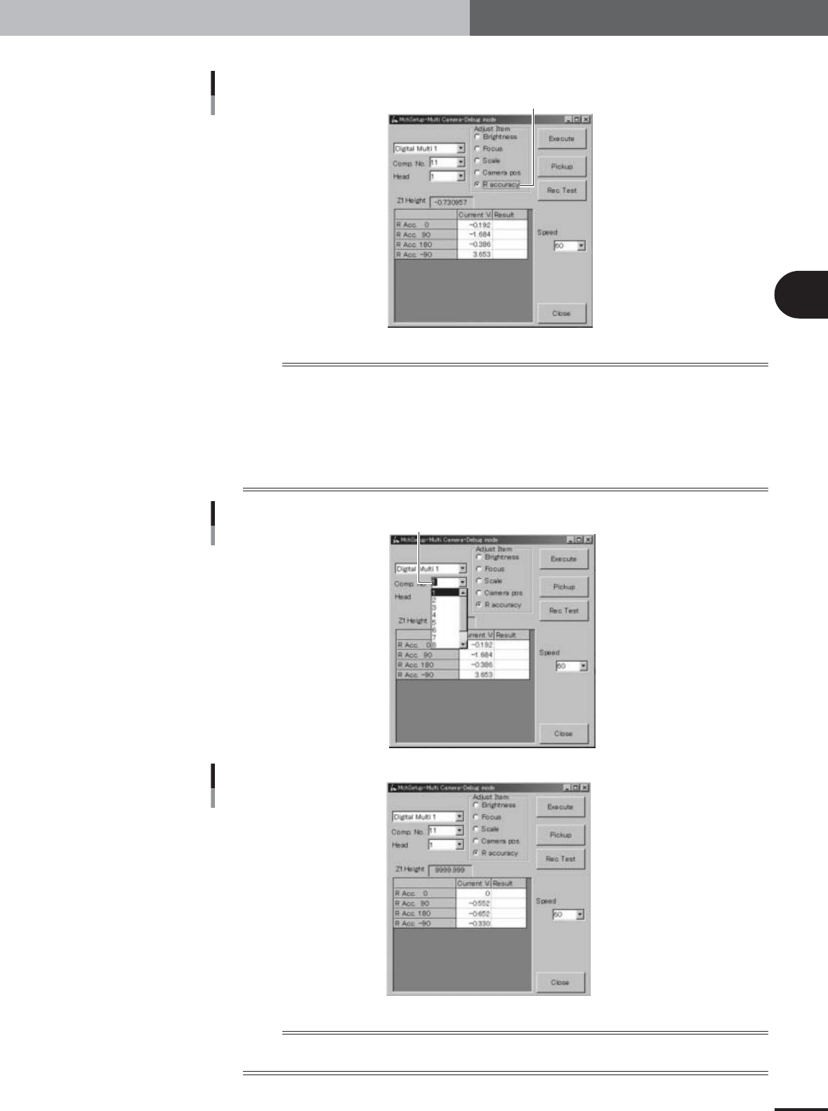
Select the "R accuracy" option button under "Adjust Item".
Selecting "R accuracy"
Select "R accuracy" option button.
27100-X9-00
n
NOTE
Also check that other items in the multi-vision camera adjustment dialog box are set as follows.
Camera : Digital Multi 1 or 2
YV100Xg family
Comp. No. : 11 (glass QFP) for Heads 1, 3, 5 and 7; Adjust Mode: Adjust Mode2
16 (SOP) for Heads 2, 4, 6 and 8; Adjust Mode: None
YV88Xg
Comp. No. : 11 (glass QFP)
Head : All
Component No. combo box
Enter "11".
27101-X9-00
R-axis accuracy
27102-X9-00
n
NOTE
Only numbers up to 10 are selectable from the drop-down list of the "Comp. No." combo box, so enter "11" from
the keyboard. In the "MCH_SETUP" PCB data, component No.11 is assigned to glass QFP (KMO-M880A-202).
3
Basic adjustments
3-34
2. R-axis accuracy offset
4
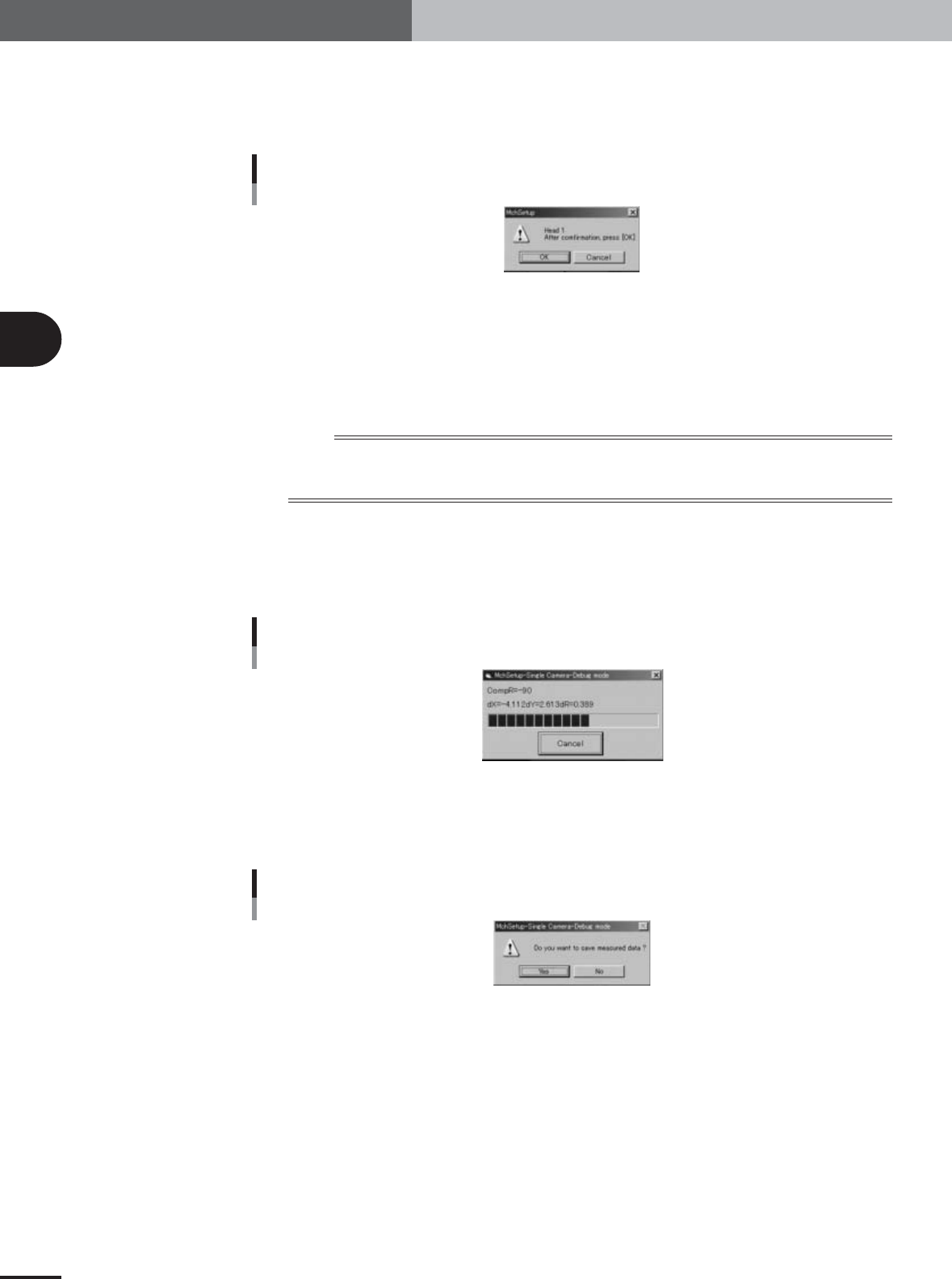
Press the [Pickup] button in the multi-vision camera adjustment
dialog box.
The head assembly moves to the component pickup position and the confirmation
dialog box appears.
Confirmation dialog box
27097-X9-00
5
Press the emergency stop button and attach the glass QFP to the
head.
Attach the glass QFP to the specified head (Head 1, 3, 5 or 7), with the pin-pattern-
printed surface facing down (toward the camera), and then press the [OK] button.
(When you are adjusting Heads 2, 4, 6 or 8, attach the SOP to the specified head.)
n
NOTE
Handle the glass QFP carefully and protect it from dust and grime. Dust, grime or nicks on the glass QFP surface
may cause recognition errors or result in poor adjustment.
Make sure the nozzle picks up the center of the glass QFP.
6
Cancel emergency stop and press the [Execute] button to start
measurements.
The head assembly moves over the multi-vision camera and the component is recog-
nized at each mounting angle to measure the R-axis accuracy offset.
Progress bar during adjustment
27098-X9-00
7
Save the results.
When the measurements are complete, a dialog box appears asking whether to save
the results. Check the results and press the [Yes] button to save them.
Save confirmation dialog box
27099-X9-00
e