Xg系列调整手册.pdf - 第30页
3 Basic adjustments 3- 8 1. Camer a parameter adjustments 7 Start measuring the lighting levels. After checking that the "Brightness" option button under "Adjust Item" is selected, press the [Execute]…
3
Basic adjustments
3-7
1. Camera parameter adjustments
5
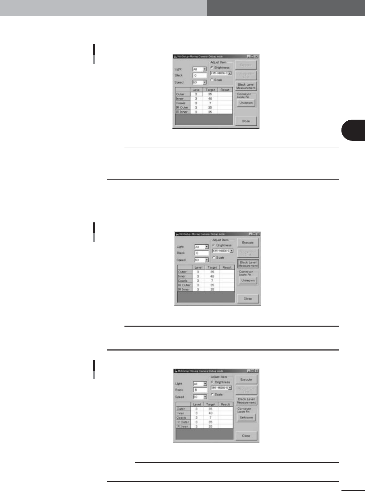
Press the [Moving Camera] button.
The moving camera adjustment dialog box appears as shown below.
Moving camera adjustment dialog box
27033-X9-00
n
NOTE
Check that the adjustment conditions in the moving camera adjustment dialog box are set as follows.
Light : All
Black : 0 or blank (The black offset value will appear after measuring the black level in the next step.)
Speed : 60
6
Measure the moving camera black level.
Place a black plate (black case floppy disk, etc.) up against the bottom of the moving
camera lighting unit so that no ambient light penetrates into the lighting unit, and
then press the [Black Level Measurement] button.
[Black Level Measurement] button
27130-X9-00
n
NOTE
A small amount of dark current is generated at the output of the CCD camera even if no light enters the CCD
(pitch black conditions). A black level measured here is used as an "offset value" for the dark current. This black
level may differ from camera to camera even between the machines of the same model.
After black level was measured
27131-X9-00
c
CAUTION
Black levels are typically 8±5. If the measured black level is greatly outside the typical range,
the camera might be defective. Please contact our sales office or sales representative.
3
Basic adjustments
3-8
1. Camera parameter adjustments
7
Start measuring the lighting levels.
After checking that the "Brightness" option button under "Adjust Item" is selected,
press the [Execute] button.
Lighting levels are measured in the order of the outer zone, inner zone, coaxial zone,
IR outer zone and IR inner zone of the lighting unit.
n
NOTE
Also check that other items in the moving camera adjustment dialog box are set as follows.
Light : All
Speed : 60
8
Proceed with the measurement.
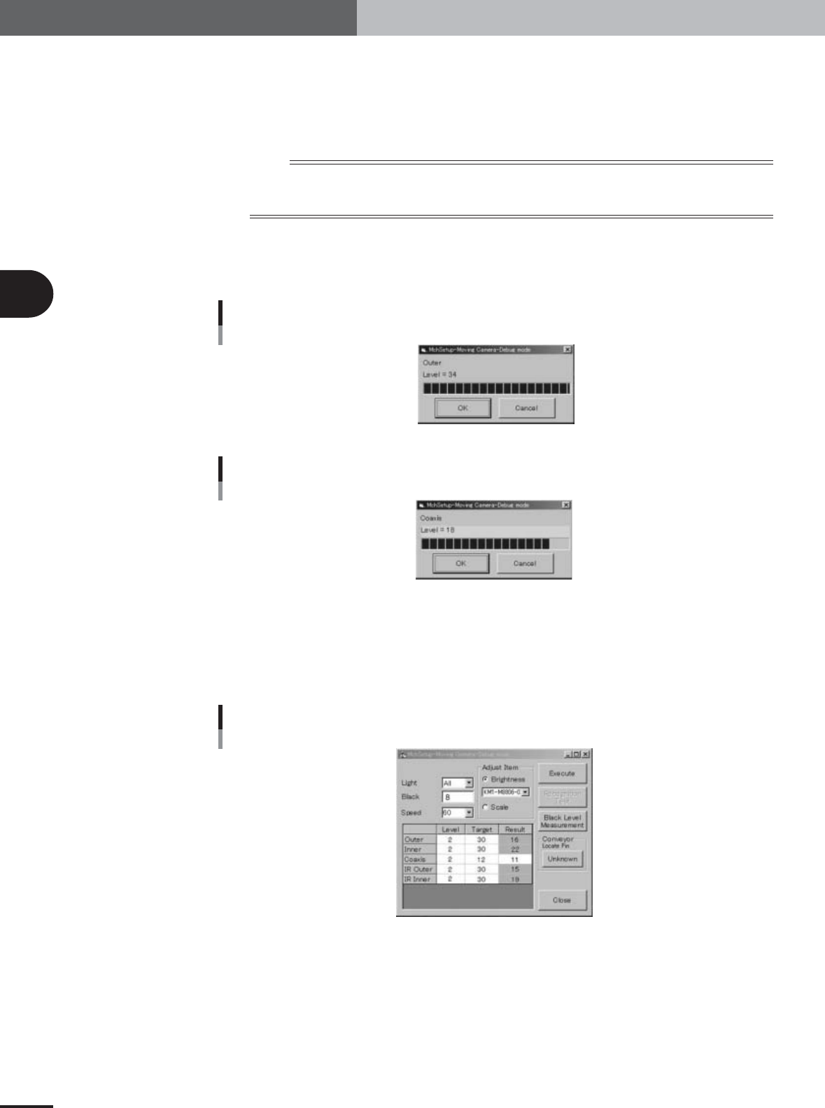
When the measurement for each zone is complete, the result dialog box appears.
Press the [OK] button to continue.
When within tolerance
27034-X9-00
When outside tolerance
27035-X9-00
9
When the measurements are complete, check the results.
Results are displayed in the "Result" column. If a result is shown in orange or red, it is
outside the tolerance range. Adjust the lighting level with the trimmer potentiometer
located on the I/O board of the head assembly, so that the lighting level is within the
tolerance range ("Target" value ± 1).
When some results are outside tolerance
27036-X9-00
3
Basic adjustments
3-9
1. Camera parameter adjustments
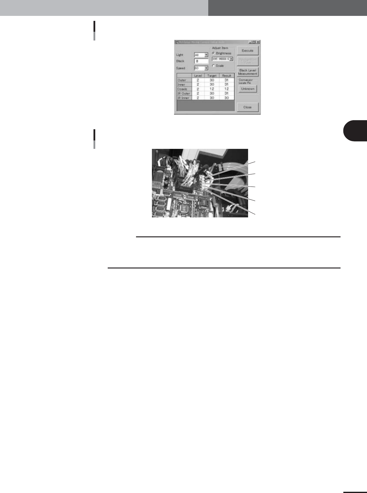
When all results are within tolerance
27037-X9-00
Trimmer potentiometers for adjusting moving camera lighting
Outer (VR1)
Inner (VR2)
Coaxis (VR3)
IR Outer (VR4)
IR Inner (VR5)
22038-X9-00
c
CAUTION
To access the trimmer potentiometers VR1 to VR5, remove the I/O board cover. They are
vertically arrayed in the same order as in the grid display in the moving camera adjustment
dialog box. The lighting levels increase by turning the trimmer potentiometers to the right. Use
an insulated adjustment screwdriver to turn the trimmer potentiometers.