Xg系列调整手册.pdf - 第24页
Table of Contents 1. Camera parameter adjustments . . . . . . . . . . . . . . . . . . . 3-3 1.1 Camer a lighting le vel adjustments . . . . . . . . . . . . . . . . . . . . . . . . 3-3 1.1.1 Adjusting the moving camera li…
2
Before beginning adjustments
2-17
2. Preparatory work
2.7 Selecting the PCB data
To perform basic adjustments (explained in Chapter 3), the PCB data named
"MCH_SETUP" must be used.
To perform FAMF adjustments (explained in Chapter 4) after all necessary basic adjust-
ments are complete, the PCB data with a name beginning with "FAMF" must be used.
Be sure to load the specified PCB data into the machine to perform each adjustment
correctly.
PCB data used for machine adjustments
Adjustment items
Basic adjustments
Camera parameters
R-axis accuracy offset
Head offset
FAMF adjustments
(using glass PCB)
FAMF adjustments
(using adjustment station)
PCB data to be used Machine models
MCH_SETUP
FAMF_71_OLD
FAMF_72_OLD
FAMF_74_OLD
FAMF_61_OLD
FAMF_62_OLD
FAMF_64_OLD
FAMFST_73
FAMFST_74
FAMFST_63
FAMFST_64
FAMFST_65
YV100Xg family
YV88Xg
YV100Xg family
YV88Xg
YV100Xg family
YV88Xg
25017-X9-00
1
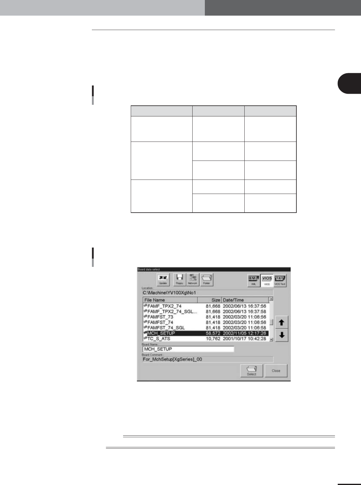
Press the [Board] button on the Setup screen.
The "Board data select" dialog box appears showing a list of registered PCB data.
Board Data Select dialog box
27024-X9-00
2
Select the PCB data.
1.Check that the [VIOS] button is pressed.
2.Line up the cursor with the PCB data you want to select and press the [OK]
button.
n
NOTE
Changes you made on the machine setting screen (VmSpec screen) are enabled after loading PCB data.

Table of Contents
1. Camera parameter adjustments . . . . . . . . . . . . . . . . . . . 3-3
1.1 Camera lighting level adjustments . . . . . . . . . . . . . . . . . . . . . . . . 3-3
1.1.1 Adjusting the moving camera lighting levels . . . . . . . . . . . . . . . . . . 3-3
1.1.2 Adjusting the multi-vision camera lighting levels . . . . . . . . . . . . . 3-10
1.1.3 Adjusting the single-vision camera lighting levels . . . . . . . . . . . . . 3-14
1.2 Camera scale calibration . . . . . . . . . . . . . . . . . . . . . . . . . . . . . . 3-18
1.2.1 Preparation for the moving camera scale calibration . . . . . . . . . . . 3-18
1.2.2 Calibrating the moving camera scale . . . . . . . . . . . . . . . . . . . . . . . 3-24
1.2.3 Calibrating the multi-vision camera scale . . . . . . . . . . . . . . . . . . . 3-25
1.2.4 Calibrating the single-vision camera scale . . . . . . . . . . . . . . . . . . . 3-28
2. R-axis accuracy offset . . . . . . . . . . . . . . . . . . . . . . . . . . 3-32
2.1
Measuring the R-axis accuracy offset with the multi-vision camera . . .
3-32
2.2
Measuring the R-axis accuracy offset with the single-vision camera . .
3-35
3. Head offset adjustments . . . . . . . . . . . . . . . . . . . . . . . . 3-38
3.1 Preparation for head offset adjustments of Heads 3, 5, and 7
(YV100Xg family) or Head 2 (YV88Xg) . . . . . . . . . . . . . . . . . . . 3-38
3.2 Adjusting the head offset of Heads 3, 5, and 7
(YV100Xg family) or Head 2 (YV88Xg) . . . . . . . . . . . . . . . . . . . 3-41
3.3 Preparation for head offset adjustments of Heads 2, 4, 6 and 8
(YV100Xg family) . . . . . . . . . . . . . . . . . . . . . . . . . . . . . . . . . . . . 3-43
3.4
Adjusting the head offset of Heads 2, 4, 6 and 8 (YV100Xg family
) . . 3-48
Chapter 3 Basic adjustments
3
Basic adjustments
3-3
1. Camera parameter adjustments
To ensure a high degree of accuracy for machine adjustments, the camera parameters such as lighting
levels and camera scales must have been adjusted correctly. This section explains how to adjust the
various parameters of each camera.
c
CAUTION
The PCB data named "MCH_SETUP" is used to adjust camera parameters such as camera
lighting levels and camera scales. Before starting adjustments, load the "MCH_SETUP" as
explained in Chapter 2.
1.1 Camera lighting level adjustments
1.1.1 Adjusting the moving camera lighting levels
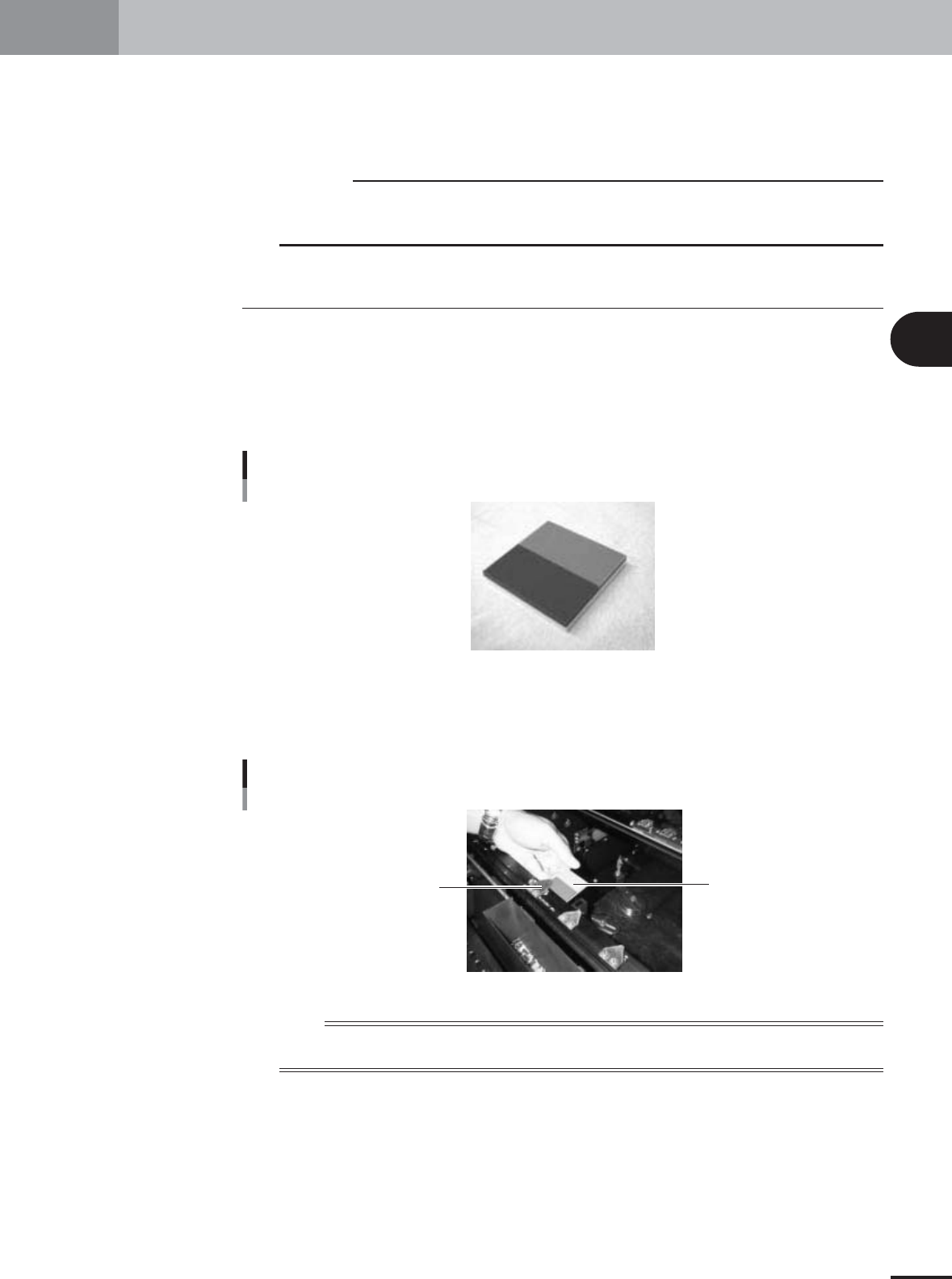
To adjust the moving camera lighting levels, a custom tool (light adjuster plate: KM1-
M8806-0XX) and trimmer potentiometers (VR1 to VR5) on the I/O board are used. Have
the light adjuster plate ready. The I/O board having the trimmer potentiometers (VR1 to
VR5) is located on the head assembly.
Light adjuster plate (KM1-M8806-0XX)
28025-X9-00
1
Set the light adjuster plate.
After making sure the machine is in emergency stop, set the light adjuster plate on the
conveyor rail just above the fixed locate pin, with the two-tone side facing up.
Setting the light adjuster plate on the conveyor
Light adjuster plate
PCB edge support plate
28026-X9-00
n
NOTE
As shown in the photo, set the dark gray side of the light adjuster plate onto the conveyor rail just above the fixed
locate pin, with the two-tone side facing up.