Xg系列调整手册.pdf - 第65页
3 Basic adjustments 3- 43 3. Head offset adjustments 3.3 Preparation for head offset adjustments of Heads 2, 4, 6 and 8 (YV100Xg family) Follow these steps to adjust the head offset of Heads 2, 4, 6 and 8 (YV100Xg family…
3
Basic adjustments
3-42
3. Head offset adjustments
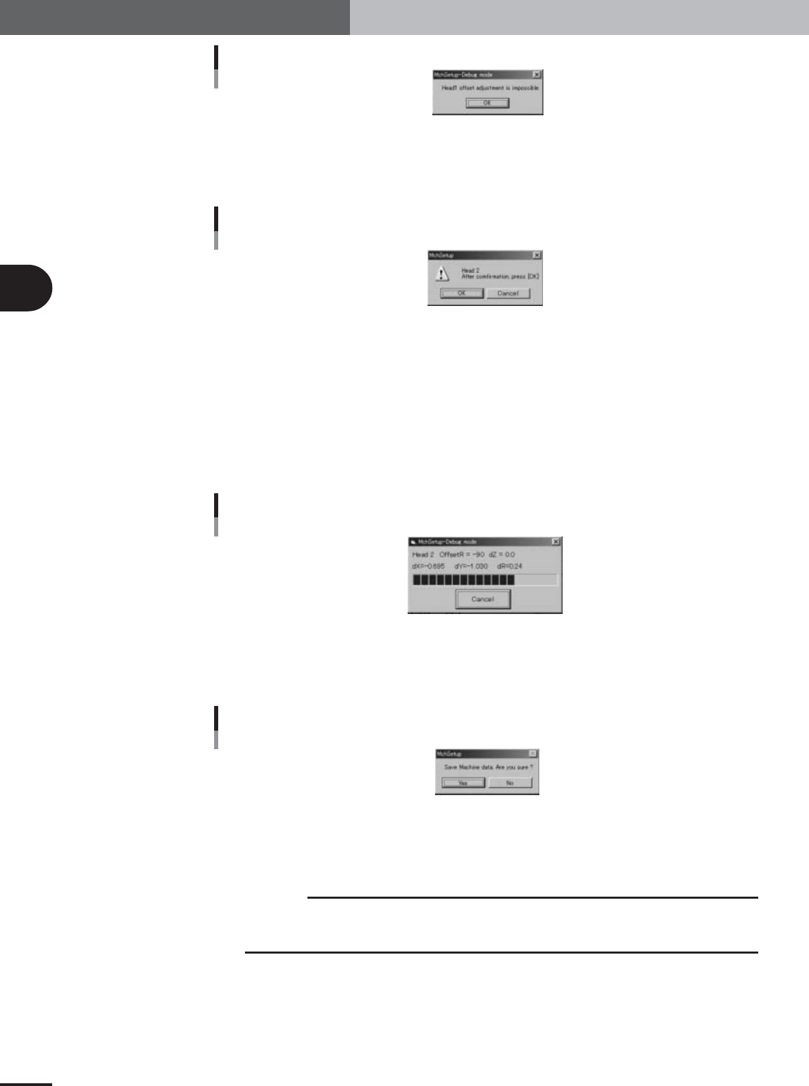
Alert message when Head 1 is selected
27109-X9-00
4
Press the [Pickup] button in the head offset adjustment dialog box.
The head assembly moves to the component pickup position and the confirmation
dialog box appears.
Confirmation dialog box
27110-X9-00
5
Press the emergency stop button and attach the glass QFP to the
specified head.
Attach the glass QFP to the nozzle of the specified head, with the pin-pattern-printed
surface facing down (toward the camera), and then press the [OK] button.
6
Cancel emergency stop and press the [Execute] button to start
adjustment.
The head assembly moves and passes repeatedly over the multi-vision camera and the
head offset is automatically measured.
Progress bar during adjustment
27111-X9-00
7
Save the result of the head offset adjustment.
When the dialog box appears asking whether to save the result, press the [Yes] button
to save it.
Save confirmation dialog box
27112-X9-00
8
Remove the glass QFP from the nozzle.
When the dialog box appears after saving the data, press the emergency stop button
and remove the glass QFP by hand from the nozzle. Then press the [OK] button.
c
CAUTION
If you press the [OK] button while the glass QFP is still being held by the nozzle, the glass QFP
will be automatically dumped and possibly damaged. Always first remove the glass QFP by
hand and then press the [OK] button.
e
e
3
Basic adjustments
3-43
3. Head offset adjustments
3.3 Preparation for head offset adjustments of Heads 2, 4,
6 and 8 (YV100Xg family)
Follow these steps to adjust the head offset of Heads 2, 4, 6 and 8 (YV100Xg family)
using 16-pin SOP components.
1
Install a tape feeder on the feeder plate.
Install a tape feeder loaded with a 16-pin SOP reel, at the feeder set position No. 9 on
the feeder plate.
2
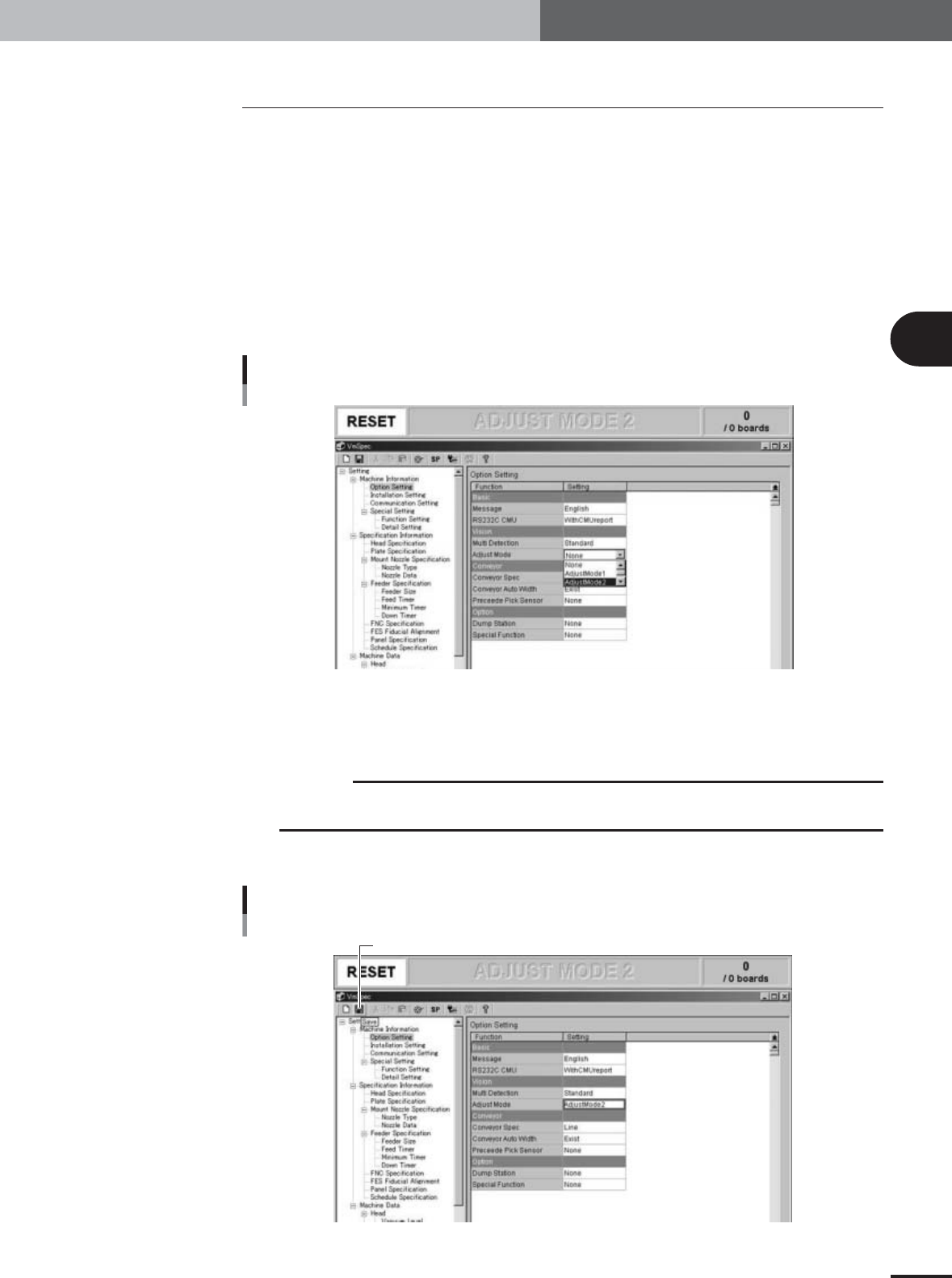
Change the "Adjust Mode" parameter.
Since SOP components are used for head offset adjustments of Heads 2, 4, 6 and 8,
the "Adjust Mode" parameter must be changed and the "MCH_SETUP" PCB data
reloaded into the machine.
1.Press the [Machine] button to display the machine setting screen (VmSpec screen).
Machine data setting window (VmSpec window)
27022-X9-00
2.In the left-hand tree view, select "Machine Information" – "Option Setting" to open
the "Option Setting" screen in the right-hand main view.
3.Set the "Adjust Mode" parameter under "Vision" to "None".
c
CAUTION
Offset adjustments using SOP components cannot be performed if the "Adjust Mode" is set to
anything other than "None".
3
Press the [Save] button on the toolbar to save the change.
[Save] button
[Save] button
27023-X9-00
3
Basic adjustments
3-44
3. Head offset adjustments
4
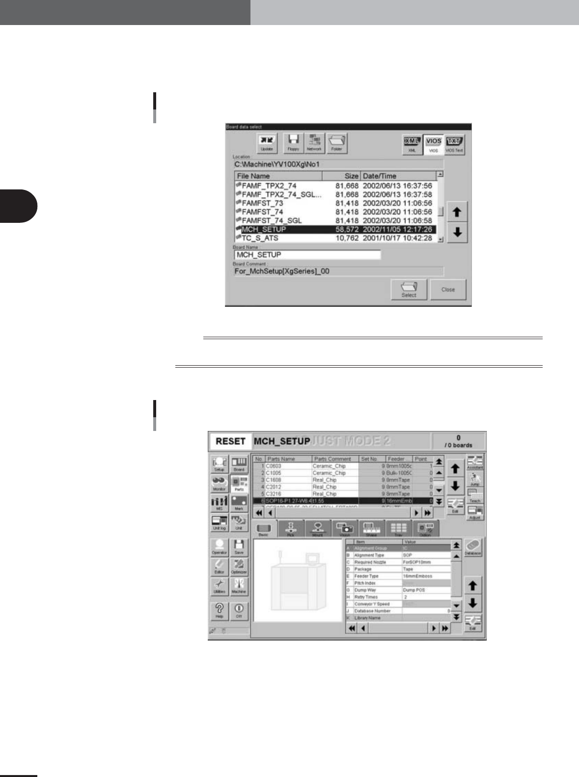
Reload the PCB data.
Open the Setup screen, press the [Board] button and select the "MCH_SETUP" PCB
data (even if it is currently loaded), to enable the changes you have made to the
machine setting.
Board Data Select dialog box
27024-X9-00
n
NOTE
After changing the machine setting, be sure to load PCB data again to enable the changes you have made to the
machine setting.
5
Press the [Parts] button to open the Parts information screen.
Parts information screen
27113-X9-00
6
Select "SOP16" (No. 6) in the upper display of the Parts information
screen.