Xg系列调整手册.pdf - 第42页
3 Basic adjustments 3- 20 1. Camer a parameter adjustments Con veyor Pushup dialog bo x 27069-X9-00 2. Press the [OK] button in the Conveyor Pushup dialog box to raise the push-up plate. 3. Set four push-up pins on the p…
3
Basic adjustments
3-19
1. Camera parameter adjustments
3
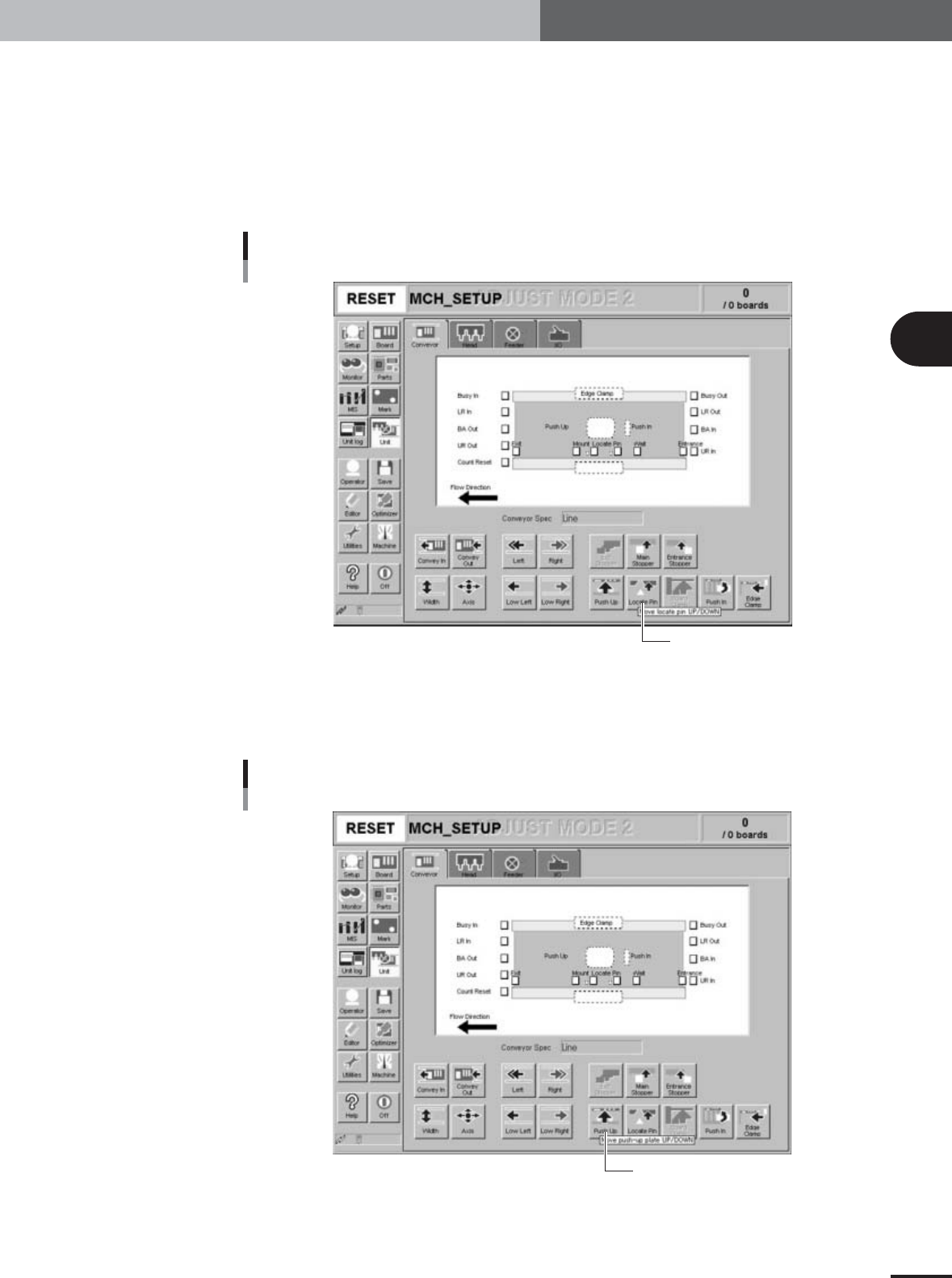
Set the glass PCB on the conveyor.
1.Press the emergency stop button and unclamp the locate pins by loosening the
lever.
2.Place the glass PCB on the conveyor, and adjust the movable locate pin position so
that the distance between the locate pins exactly matches the distance between the
positioning holes in the metal frame of the glass PCB.
3.Clamp the locate pins and press the [Locate Pin] button to raise the locate pins so
that they engage with the positioning holes in the metal frame of the glass PCB.
[Locate Pin] button
[Locate Pin] button
27067-X9-00
4
Set push-up pins to support the glass PCB from the bottom.
1.Cancel emergency stop and press the [Push Up] button.
The Conveyor Pushup dialog box appears.
[Push Up] button
[Push Up] button
27068-X9-00
e
3
Basic adjustments
3-20
1. Camera parameter adjustments
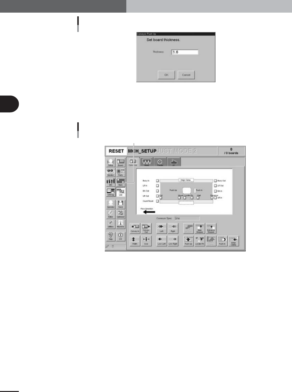
Conveyor Pushup dialog box
27069-X9-00
2.Press the [OK] button in the Conveyor Pushup dialog box to raise the push-up plate.
3.Set four push-up pins on the push-up plate just under each of the four corners of
the glass PCB.
5
Press the [Mark] button to open the Mark information screen.
[Mark] button
[Mark] button
27070-X9-00
3
Basic adjustments
3-21
1. Camera parameter adjustments
6
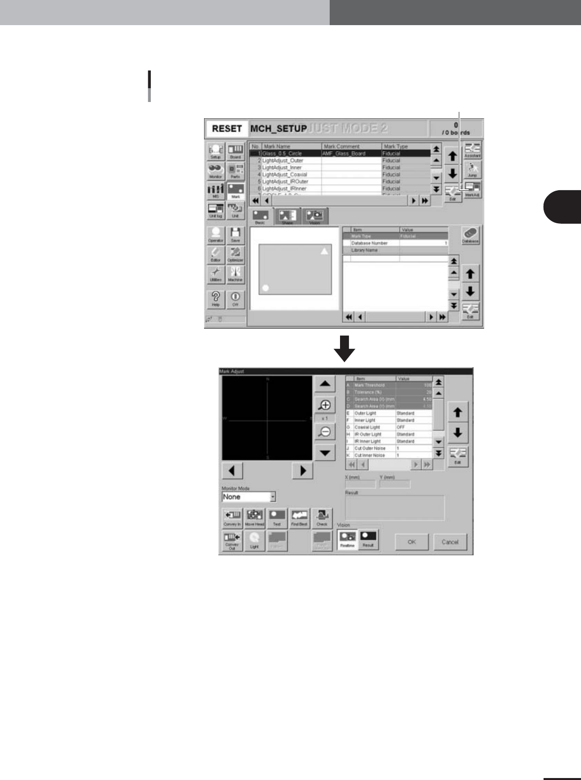
Select "Mark No.1" and press the [Mark Adj] button.
The Mark Adjust window opens.
[Mark Adj] button and Mark Adjust window
[Mark Adj] button
27071-X9-00