Xg系列调整手册.pdf - 第39页
3 Basic adjustments 3- 17 1. Camer a parameter adjustments 8 Save the result of the coaxial lighting level adjustment. When the dialog box appears asking whether to save the result, press the [Yes] button to save it and …
3
Basic adjustments
3-16
1. Camera parameter adjustments
5
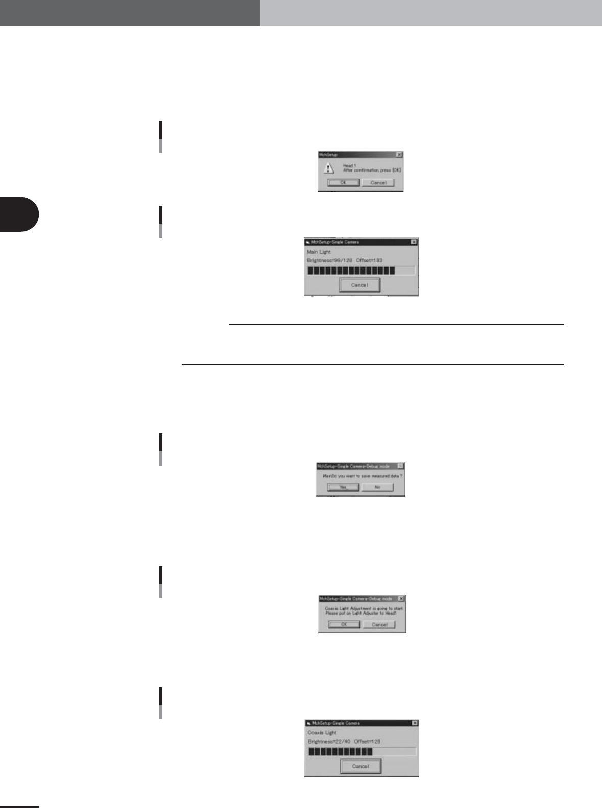
Start the main lighting level adjustment.
1.Cancel emergency stop and press the [Execute] button.
The confirmation dialog box appears.
2.Press the [OK] button to start adjustment.
The head assembly moves to a position above the single-vision camera, and the
main lighting level is automatically adjusted.
Confirmation dialog box
Main light level
27056-X9-00
Progress bar during adjustment
Main light level
27057-X9-00
c
CAUTION
The single-vision camera adjustments are made automatically. Do not make adjustments in an
environment that greatly differs from the actual production environment. Doing so may lead to
inaccurate data settings, making component recognition unreliable.
6
Save the result of the main lighting level adjustment.
When the dialog box appears asking whether to save the result, press the [Yes] button
to save it and continue the adjustment.
Typical main lighting level: 128±2
Save confirmation dialog box
Main light level
27058-X9-00
7
Next, start the coaxial lighting level adjustment.
1.When the dialog box for the coaxial lighting level appears, press the emergency stop
button, turn the light adjuster plate upside down, and then reattach it to Head 1,
with the white surface facing down.
Confirmation dialog box
Coaxial light level
27059-X9-00
2.Press the [OK] button to start adjustment.
The head assembly moves to a position above the single-vision camera, and the
coaxial lighting level is automatically adjusted.
Progress bar during adjustment
Coaxial light level
27060-X9-00
e
3
Basic adjustments
3-17
1. Camera parameter adjustments
8
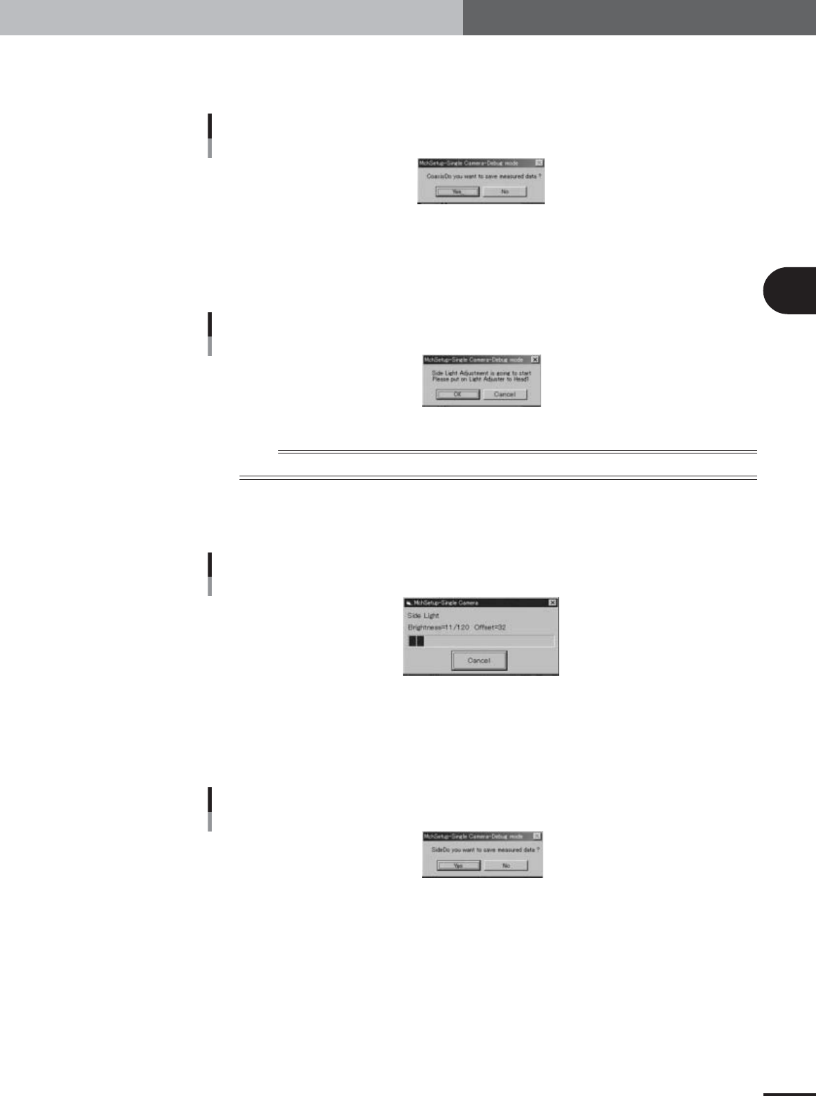
Save the result of the coaxial lighting level adjustment.
When the dialog box appears asking whether to save the result, press the [Yes] button
to save it and continue the adjustment.
Save confirmation dialog box
Coaxial light level
27061-X9-00
9
Next, start the side lighting level adjustment.
1.When the dialog box for the side lighting level appears, press the emergency stop
button, remove the light adjuster plate from Head 1 and attach the light adjuster
plate-2 (KV7-M8806-0XX) to Head 1, with the glossy surface facing up.
Confirmation dialog box
Side light level
27062-X9-00
n
NOTE
Attach the light adjuster plate-2 (KV7-M8806-0XX) to Head 1 so that the glossy surface faces up.
2.Press the [OK] button to start the adjustment.
The head assembly moves to a position above the single-vision camera, and the
side lighting level is automatically adjusted.
Progress bar during adjustment
Side light level
27063-X9-00
0
Save the result of the side lighting level adjustment.
When the dialog box appears asking whether to save the result, press the [Yes] button
to save it.
Typical side lighting level: 120±2
Save confirmation dialog box
Side light level
27064-X9-00
e
3
Basic adjustments
3-18
1. Camera parameter adjustments
1.2 Camera scale calibration
1.2.1 Preparation for the moving camera scale calibration
To calibrate the moving camera scale, a custom-designed glass PCB is used. The machine
must be set to "Adjust Mode2" (see sections 2.5 and 2.6 in Chapter 2) and the
"MCH_SETUP" PCB data loaded into the machine (see section 2.7 in Chapter 2).
c
CAUTION
Before starting the camera scale calibration, the machine should be warmed up for 30 minutes
or more. (See section 2.3, " Warming up the machine".)
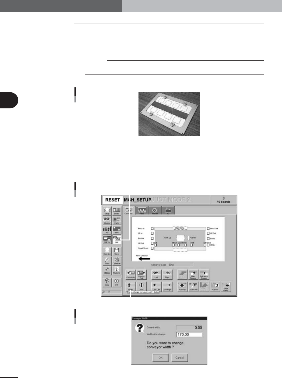
1
Have the glass PCB ready.
Glass PCB
28012-X9-00
2
Adjust the conveyor width.
1.Open the [Unit]-[Conveyor] tab screen and press the [Conveyor] button.
The Conveyor Width dialog box appears.
2.Check that the conveyor width after change is set to "170" (mm) and press the
[OK] button.
The conveyor rail changes to the specified width.
[Unit]-[Conveyor] tab screen
[Unit] button
[Width] button
27065-X9-00
Conveyor width dialog box
27066-X9-00