Xg系列调整手册.pdf - 第35页
3 Basic adjustments 3- 13 1. Camer a parameter adjustments 0 Next, start the side lighting level adjustment. 1. When the dialog box for the side lighting level appears, press the emergency stop button, remove the light a…
3
Basic adjustments
3-12
1. Camera parameter adjustments
7
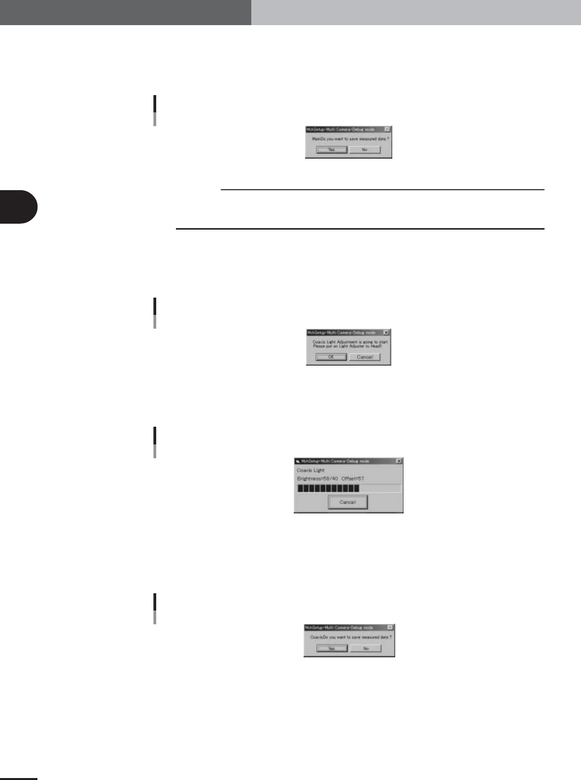
Save the result of the main lighting level adjustment.
When the dialog box appears asking whether to save the result, press the [Yes] button
to save it and continue the adjustment.
Typical main lighting level: 128±2
Save confirmation dialog box
Main light level
27045-X9-00
c
CAUTION
A sandglass cursor appears during saving of the result. Do not attempt any operation until the
sandglass cursor disappears. (This holds true for all adjustments of the main, side and coaxial
lighting levels.)
8
Next, start the coaxial lighting level adjustment.
1.When the dialog box for the coaxial lighting level appears, press the emergency stop
button, turn the light adjuster plate upside down, and then reattach it to Head 1,
with the white surface facing down.
Confirmation dialog box
Coaxial light level
27046-X9-00
2.Press the [OK] button to start adjustment.
The head assembly moves and passes repeatedly over the multi-vision camera, and
the coaxial lighting level is automatically adjusted.
Progress bar during adjustment
Coaxial light level
27047-X9-00
9
Save the result of the coaxial lighting level adjustment.
When the dialog box appears asking whether to save the result, press the [Yes] button
to save it and continue the adjustment.
Typical coaxial lighting level: 40±2
Save confirmation dialog box
Coaxial light level
27048-X9-00
e
3
Basic adjustments
3-13
1. Camera parameter adjustments
0
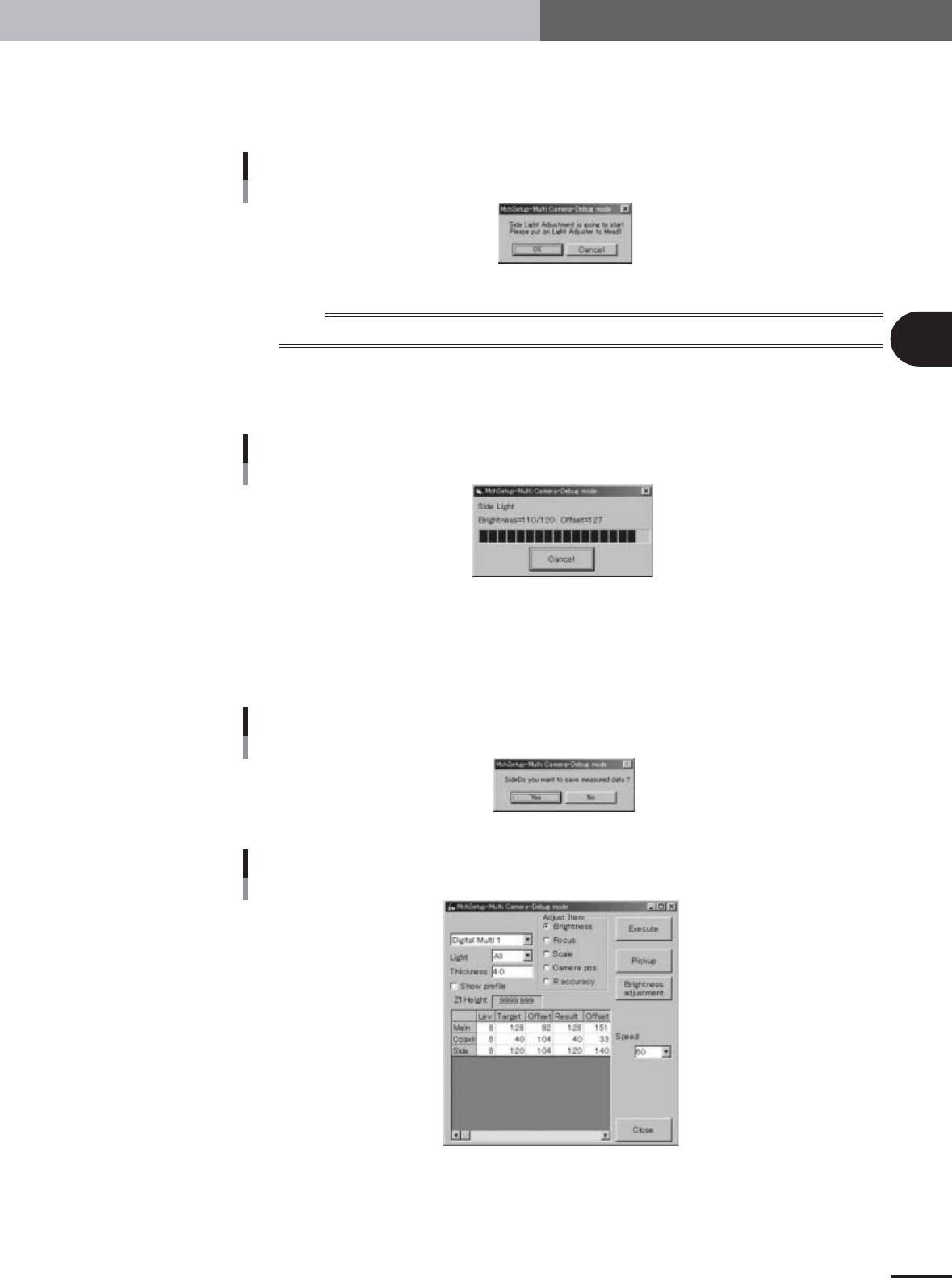
Next, start the side lighting level adjustment.
1.When the dialog box for the side lighting level appears, press the emergency stop
button, remove the light adjuster plate from Head 1. Attach the light adjuster plate-
2 (KV7-M8806-0XX) to Head 1, with the glossy surface facing up.
Confirmation dialog box
Side light level
27049-X9-00
n
NOTE
Attach the light adjuster plate-2 (KV7-M8806-0XX) to Head 1 so that the glossy surface faces up.
2.Press the [OK] button to start adjustment.
The head assembly moves and passes repeatedly over the multi-vision camera, and
the side lighting level is automatically adjusted.
Progress bar during adjustment
Side light level
27050-X9-00
q
Save the result of the side lighting level adjustment.
When the dialog box appears asking whether to save the result, press the [Yes] button
to save it.
Typical side lighting level: 120±2
Save confirmation dialog box
Side light level
27051-X9-00
Result display after adjustment
27052-X9-00
e
3
Basic adjustments
3-14
1. Camera parameter adjustments
1.1.3 Adjusting the single-vision camera lighting levels
To adjust the lighting levels for an optional single-vision camera, the same light adjuster
plates as for multi-vision camera adjustments are used. Have these light adjuster plates
ready.
1
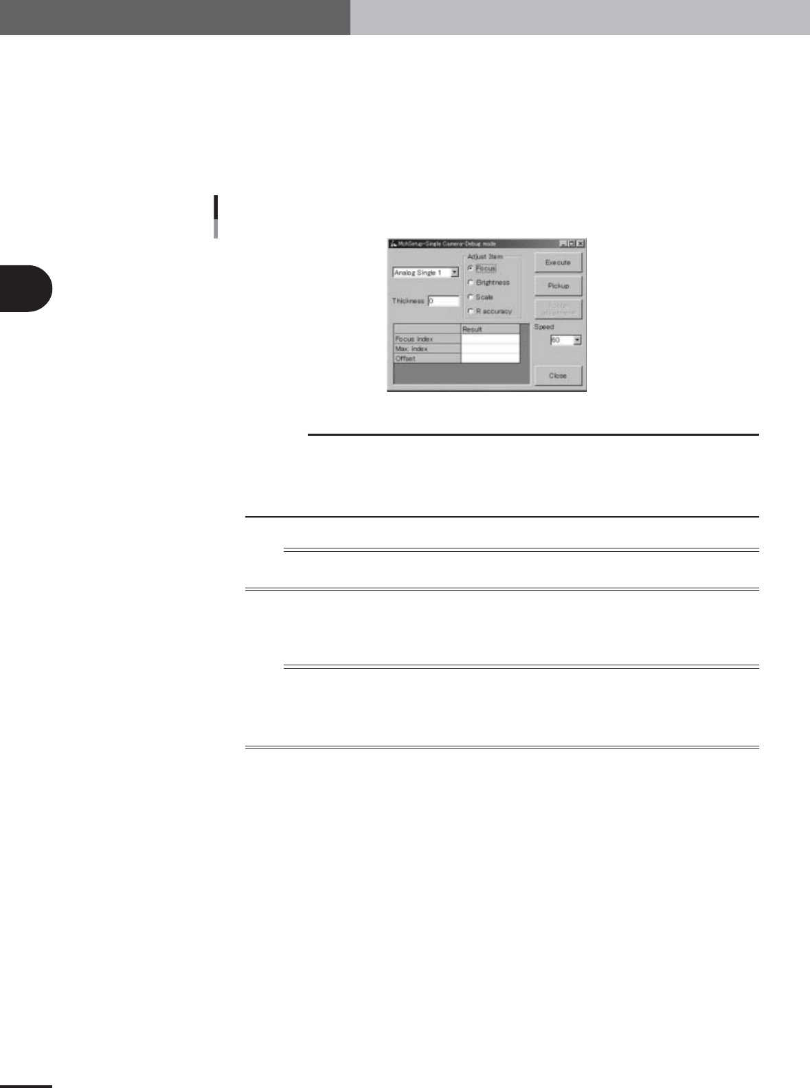
Press the [Single Camera] button in the adjustment utility menu
window.
The single-vision camera adjustment dialog box appears as shown below.
Single-vision camera adjustment dialog box
27053-X9-00
c
CAUTION
Single-vision cameras are optional. The number of single-vision cameras installed in one
machine depends on the machine's specifications. (No single-vision camera is installed in
standard specification machines.) Check your machine's specifications.
In the single-vision camera adjustment dialog box, the single-vision camera number is shown
as "Analog single 1" or "Analog single 2" when the second single-vision camera is installed.
n
NOTE
In the case of standard machines with no single-vision camera installed, the buttons in the dialog box are grayed
out.
2
Check that the "Brightness" option button under "Adjust Item" is
selected.
n
NOTE
Also check that other items in the single-vision camera adjustment dialog box are set as follows.
Camera : Analog single 1 or 2
Light : All
Thickness : 4.0
Speed : 60