Xg系列调整手册.pdf - 第34页
3 Basic adjustments 3- 12 1. Camer a parameter adjustments 7 Save the result of the main lighting level adjustment. When the dialog box appears asking whether to save the result, press the [Yes] button to save it and con…
3
Basic adjustments
3-11
1. Camera parameter adjustments
3
Press the [Pickup] button in the multi-vision camera adjustment
dialog box.
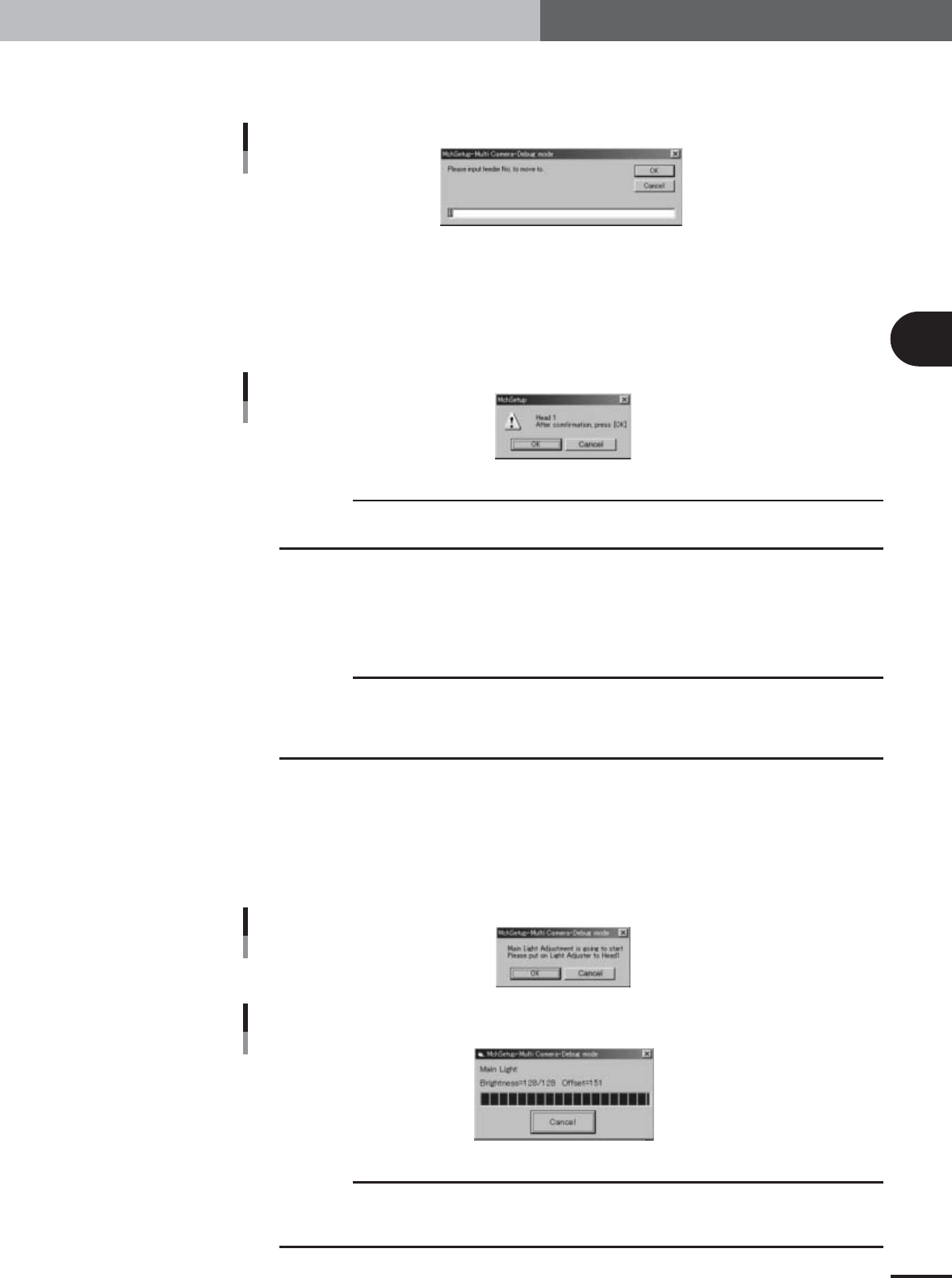
The feeder set No. entry dialog box appears.
Feeder No. entry dialog box
27041-X9-00
4
Specify the pickup position to attach the light adjuster plates to Head
1.
In the feeder set No. entry box, enter the feeder set No. at a position where you can
easily attach the light adjuster plates to Head 1 and then press the [OK] button.
The head assembly will move to the specified pickup position and the confirmation
dialog box appears.
Confirmation dialog box
27042-X9-00
c
CAUTION
If the nozzle of Head 1 is not "Type 74" at this point, then it will be automatically changed to a
Type 74 nozzle.
5
Press the emergency stop button and attach the light adjuster plate to
Head 1.
Attach the light adjuster plate (KM1-M8806-0XX) to Head 1, with the two-tone
surface facing down and the light gray area positioned just under the nozzle tip.
c
CAUTION
The light adjuster plate (KM1-M8806-0XX) is used to adjust the main and coaxial lighting levels,
while the light adjuster plate-2 (KV7-M8806-0XX) is used to adjust the side lighting level.
Adjustments will be made in the order of: the main lighting level, coaxial light level and side
lighting level.
6
Start the main lighting level adjustment.
1.Cancel emergency stop and press the [Execute] button.
The confirmation dialog box appears.
2.Press the [OK] button to start adjustment.
The head assembly moves and passes repeatedly over the multi-vision camera, and
the main lighting level is automatically adjusted.
Start dialog box
27043-X9-00
Progress bar during adjustment
Main light level
27044-X9-00
c
CAUTION
The multi-vision camera adjustments are made automatically. Do not make adjustments in an
environment that greatly differs from the actual production environment. Doing so may lead to
inaccurate data settings, making component recognition unreliable.
e
3
Basic adjustments
3-12
1. Camera parameter adjustments
7
Save the result of the main lighting level adjustment.
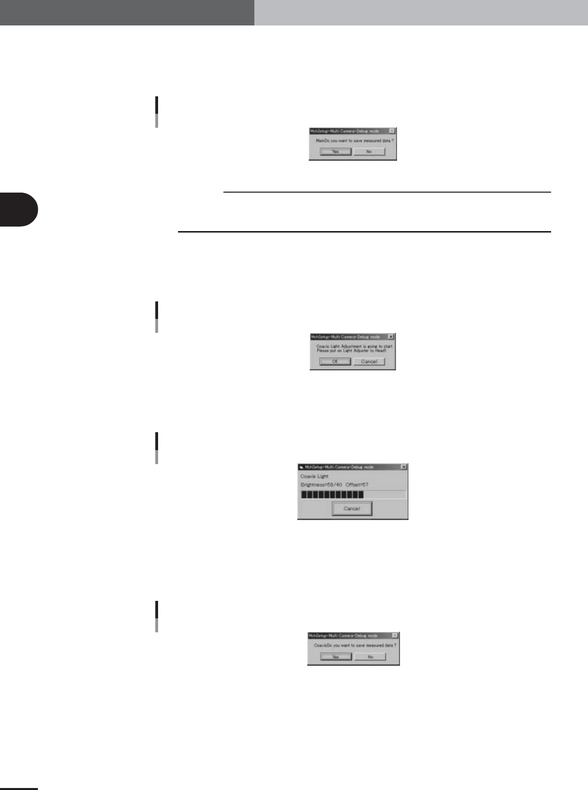
When the dialog box appears asking whether to save the result, press the [Yes] button
to save it and continue the adjustment.
Typical main lighting level: 128±2
Save confirmation dialog box
Main light level
27045-X9-00
c
CAUTION
A sandglass cursor appears during saving of the result. Do not attempt any operation until the
sandglass cursor disappears. (This holds true for all adjustments of the main, side and coaxial
lighting levels.)
8
Next, start the coaxial lighting level adjustment.
1.When the dialog box for the coaxial lighting level appears, press the emergency stop
button, turn the light adjuster plate upside down, and then reattach it to Head 1,
with the white surface facing down.
Confirmation dialog box
Coaxial light level
27046-X9-00
2.Press the [OK] button to start adjustment.
The head assembly moves and passes repeatedly over the multi-vision camera, and
the coaxial lighting level is automatically adjusted.
Progress bar during adjustment
Coaxial light level
27047-X9-00
9
Save the result of the coaxial lighting level adjustment.
When the dialog box appears asking whether to save the result, press the [Yes] button
to save it and continue the adjustment.
Typical coaxial lighting level: 40±2
Save confirmation dialog box
Coaxial light level
27048-X9-00
e
3
Basic adjustments
3-13
1. Camera parameter adjustments
0
Next, start the side lighting level adjustment.
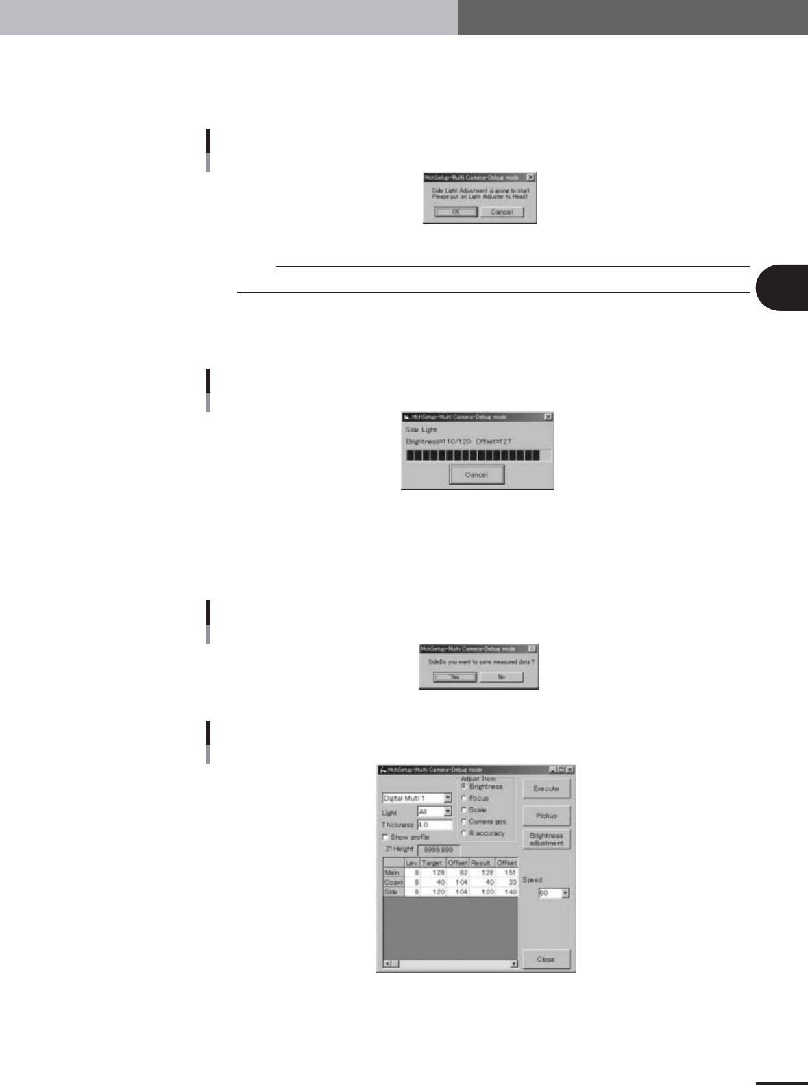
1.When the dialog box for the side lighting level appears, press the emergency stop
button, remove the light adjuster plate from Head 1. Attach the light adjuster plate-
2 (KV7-M8806-0XX) to Head 1, with the glossy surface facing up.
Confirmation dialog box
Side light level
27049-X9-00
n
NOTE
Attach the light adjuster plate-2 (KV7-M8806-0XX) to Head 1 so that the glossy surface faces up.
2.Press the [OK] button to start adjustment.
The head assembly moves and passes repeatedly over the multi-vision camera, and
the side lighting level is automatically adjusted.
Progress bar during adjustment
Side light level
27050-X9-00
q
Save the result of the side lighting level adjustment.
When the dialog box appears asking whether to save the result, press the [Yes] button
to save it.
Typical side lighting level: 120±2
Save confirmation dialog box
Side light level
27051-X9-00
Result display after adjustment
27052-X9-00
e