Xg系列调整手册.pdf - 第31页
3 Basic adjustments 3- 9 1. Camer a parameter adjustments When all results are within tolerance 27037-X9-00 Tr immer potentiometers f or adjusting moving camera lighting Outer (VR1) Inner (VR2) Coaxis (VR3) IR Outer (VR4…
3
Basic adjustments
3-8
1. Camera parameter adjustments
7
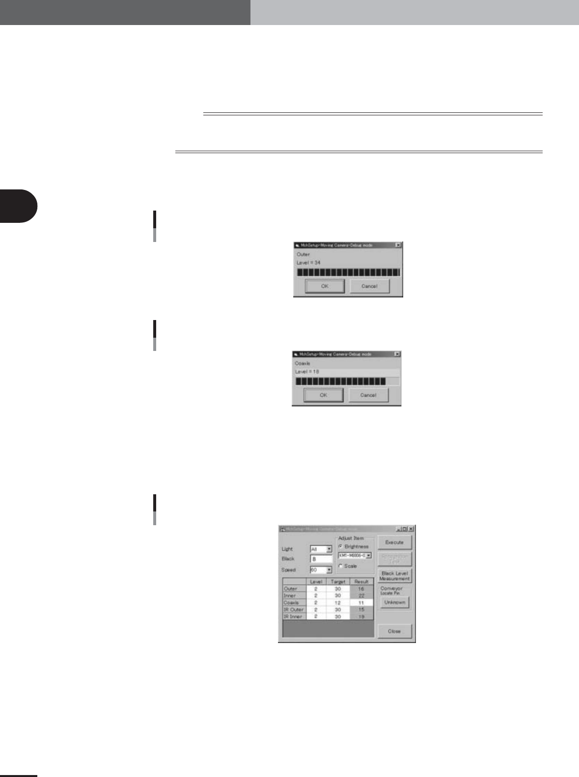
Start measuring the lighting levels.
After checking that the "Brightness" option button under "Adjust Item" is selected,
press the [Execute] button.
Lighting levels are measured in the order of the outer zone, inner zone, coaxial zone,
IR outer zone and IR inner zone of the lighting unit.
n
NOTE
Also check that other items in the moving camera adjustment dialog box are set as follows.
Light : All
Speed : 60
8
Proceed with the measurement.
When the measurement for each zone is complete, the result dialog box appears.
Press the [OK] button to continue.
When within tolerance
27034-X9-00
When outside tolerance
27035-X9-00
9
When the measurements are complete, check the results.
Results are displayed in the "Result" column. If a result is shown in orange or red, it is
outside the tolerance range. Adjust the lighting level with the trimmer potentiometer
located on the I/O board of the head assembly, so that the lighting level is within the
tolerance range ("Target" value ± 1).
When some results are outside tolerance
27036-X9-00
3
Basic adjustments
3-9
1. Camera parameter adjustments
When all results are within tolerance
27037-X9-00
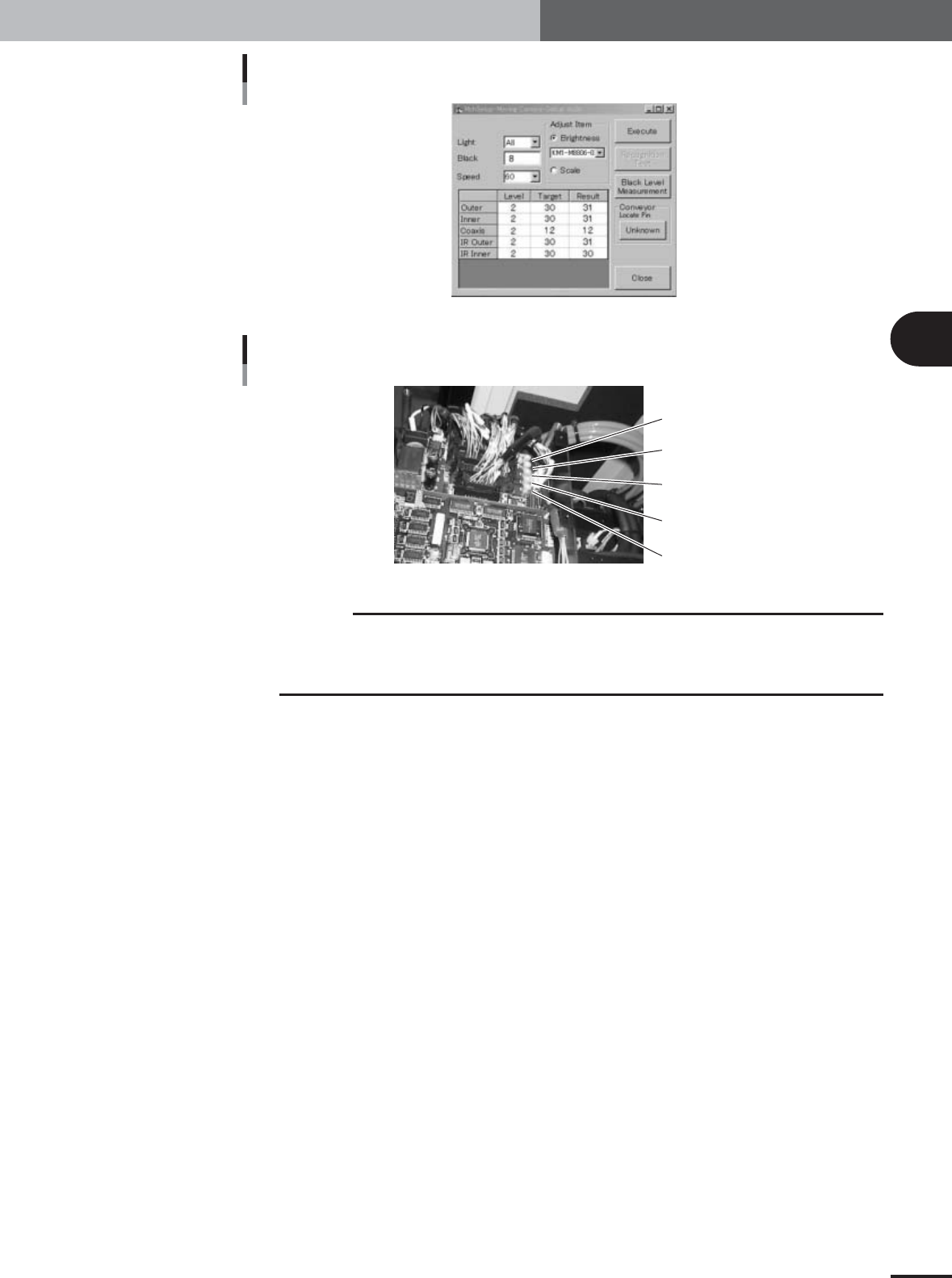
Trimmer potentiometers for adjusting moving camera lighting
Outer (VR1)
Inner (VR2)
Coaxis (VR3)
IR Outer (VR4)
IR Inner (VR5)
22038-X9-00
c
CAUTION
To access the trimmer potentiometers VR1 to VR5, remove the I/O board cover. They are
vertically arrayed in the same order as in the grid display in the moving camera adjustment
dialog box. The lighting levels increase by turning the trimmer potentiometers to the right. Use
an insulated adjustment screwdriver to turn the trimmer potentiometers.
3
Basic adjustments
3-10
1. Camera parameter adjustments
1.1.2 Adjusting the multi-vision camera lighting levels
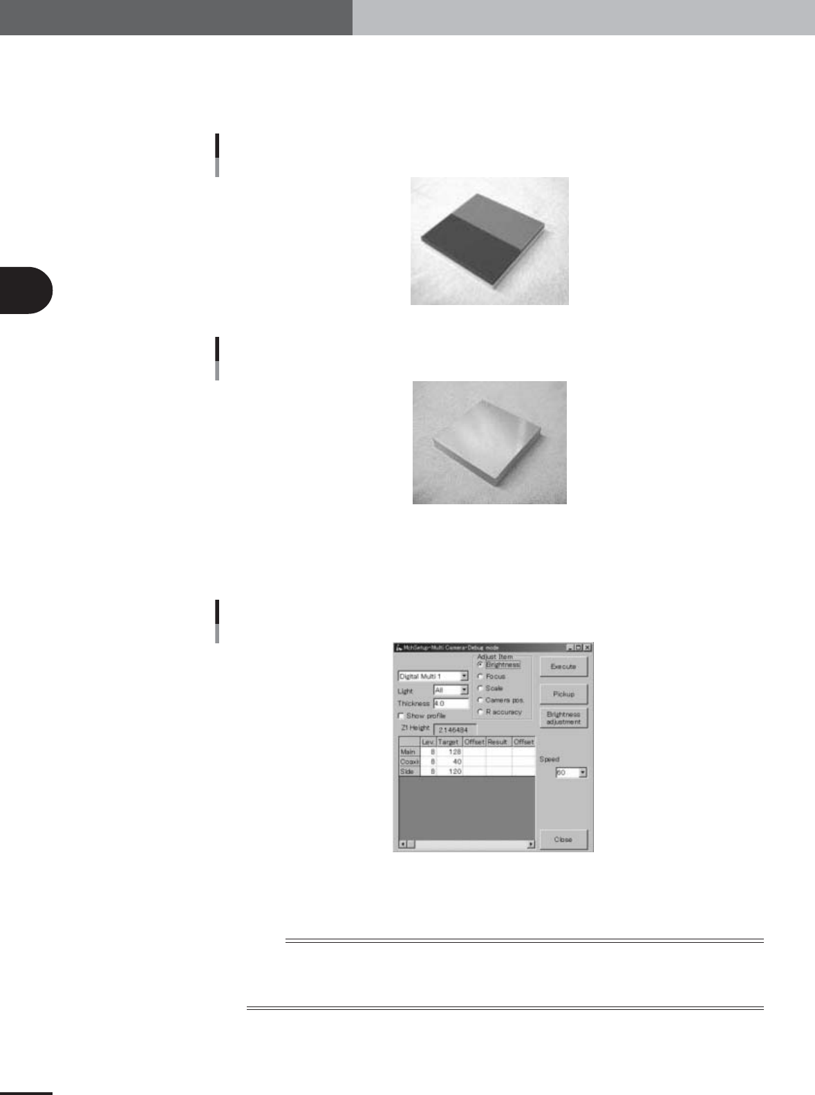
To perform automatic adjustment of the multi-vision camera lighting levels, two custom
tools (light adjuster plate: KM1-M8806-0XX and light adjuster plate-2: KV7-M8806-
0XX) are used. Have these light adjuster plates ready.
Light adjuster plate (KM1-M8806-0XX)
28025-X9-00
Light adjuster plate-2 (KV7-M8806-0XX)
28039-X9-00
1
Press the [Multi Camera] button in the adjustment utility menu
window.
The multi-vision camera adjustment dialog box appears as shown below.
Multi-vision camera adjustment dialog box
27040-X9-00
2
Check that the "Brightness" option button under "Adjust Item" is
selected.
n
NOTE
Also check that other items in the multi-vision camera adjustment dialog box are set as follows.
Light : All
Thickness : 4.0
Speed : 60