Xg系列调整手册.pdf - 第8页
Table of Contents 1. Machine adjustment flow . . . . . . . . . . . . . . . . . . . . . . . . . 2-3 2. Preparatory work . . . . . . . . . . . . . . . . . . . . . . . . . . . . . . . 2-4 2.1 System data backup . . . . . . …
1
How to use this manual
1-6
4. Applicable models
This manual applies to the following YAMAHA surface mounter models that operate with VGOS
software.
Applicable models
YV88Xg
YV100Xg
YV180Xg
YV100XTg
Reference
This manual refers to the YV100Xg, YV180Xg and YV100XTg as the YV100Xg family, since they have
basically the same type of 8 in-line heads.
c
CAUTION
FAMF adjustments described in this manual cannot be performed on any machine other than
the above models operating with YGOS. Use this manual only when adjusting the above
applicable models.

Table of Contents
1. Machine adjustment flow. . . . . . . . . . . . . . . . . . . . . . . . . 2-3
2. Preparatory work . . . . . . . . . . . . . . . . . . . . . . . . . . . . . . . 2-4
2.1 System data backup . . . . . . . . . . . . . . . . . . . . . . . . . . . . . . . . . . . 2-4
2.2 Restoring the system data . . . . . . . . . . . . . . . . . . . . . . . . . . . . . . 2-7
2.3 Warming up the machine . . . . . . . . . . . . . . . . . . . . . . . . . . . . . . 2-10
2.4 How to start the adjustment utility. . . . . . . . . . . . . . . . . . . . . . . 2-12
2.5 Changing the machine setting . . . . . . . . . . . . . . . . . . . . . . . . . . 2-14
2.6 Changing the machine setting (when needed during adjustment) 2-16
2.7 Selecting the PCB data . . . . . . . . . . . . . . . . . . . . . . . . . . . . . . . . 2-17
Chapter 2 Before beginning adjustments
2
Before beginning adjustments
2-3
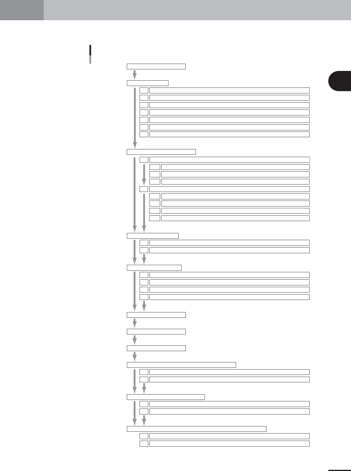
1. Machine adjustment flow
This section explains a typical flow of FAMF adjustments including preparatory work and basic adjust-
ments.
Machine adjustment flow chart
1.Machine adjustment flow
2.Preparatory work
System data backup
Restoring the system data
Warming up the machine
How to start the adjustment utility.
Changing the machine setting
Changing the machine setting (when needed during adjustment)
Selecting the PCB data
2.1
2.2
2.3
2.4
2.5
2.6
2.7
Chapter 2
Chapter 3
Chapter 4
1.Camera parameter adjustments
Camera lighting level adjustments1.1
Adjusting the moving camera lighting levels1.1.1
Adjusting the single-vision camera lighting levels1.1.3
Adjusting the multi-vision camera lighting levels1.1.2
Preparation for the moving camera scale calibration1.2.1
Camera scale calibration1.2
Calibrating the moving camera scale1.2.2
Calibrating the multi-vision camera scale1.2.3
Calibrating the single-vision camera scale1.2.4
2.R-axis accuracy offset
Measuring the R-axis accuracy offset with the multi-vision camera2.1
Measuring the R-axis accuracy offset with the single-vision camera
2.2
3.Head offset adjustments
Preparation for head offset adjustments of Heads 3, 5, and 7 (YV100Xg family) or Head 2 (YV88Xg)3.1
Adjusting the head offset of Heads 3, 5, and 7 (YV100Xg family) or Head 2 (YV88Xg)
3.2
Preparation for head offset adjustments of Heads 2, 4, 6 and 8 (YV100Xg family)3.3
Adjusting the head offset of Heads 2, 4, 6 and 8 (YV100Xg family)
3.4
1.FAMF adjustment flow
2.Preparing the glass PCB
3.Warming up the machine
4.FAMF adjustments using ceramic chip components
Preparation4.1
Performing FAMF adjustments using ceramic chip components
4.2
5.FAMF adjustments using glass QFP
Preparation5.1
Performing FAMF adjustments using glass QFP
5.2
6.FAMF adjustments using the FAMF station (reference description)
Setting up for the FAMF station6.1
FAMF adjustments using the FAMF station and glass QFP
6.2
25002-X9-00