Xg系列调整手册.pdf - 第32页
3 Basic adjustments 3- 10 1. Camer a parameter adjustments 1.1.2 Adjusting the multi-vision camera lighting levels To perform automatic adjustment of the multi-vision camera lighting levels, two custom tools (light adjus…
3
Basic adjustments
3-9
1. Camera parameter adjustments
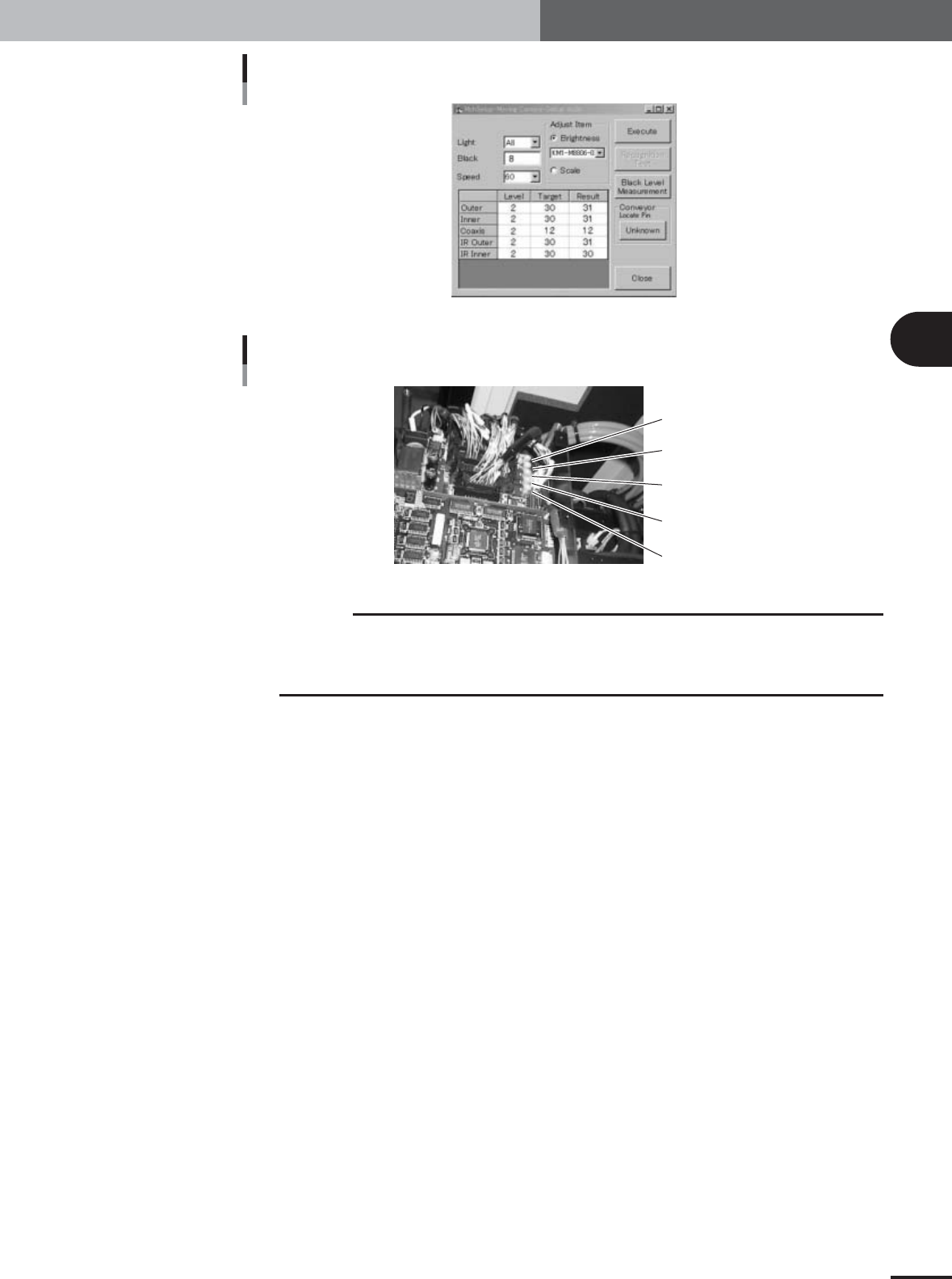
When all results are within tolerance
27037-X9-00
Trimmer potentiometers for adjusting moving camera lighting
Outer (VR1)
Inner (VR2)
Coaxis (VR3)
IR Outer (VR4)
IR Inner (VR5)
22038-X9-00
c
CAUTION
To access the trimmer potentiometers VR1 to VR5, remove the I/O board cover. They are
vertically arrayed in the same order as in the grid display in the moving camera adjustment
dialog box. The lighting levels increase by turning the trimmer potentiometers to the right. Use
an insulated adjustment screwdriver to turn the trimmer potentiometers.
3
Basic adjustments
3-10
1. Camera parameter adjustments
1.1.2 Adjusting the multi-vision camera lighting levels
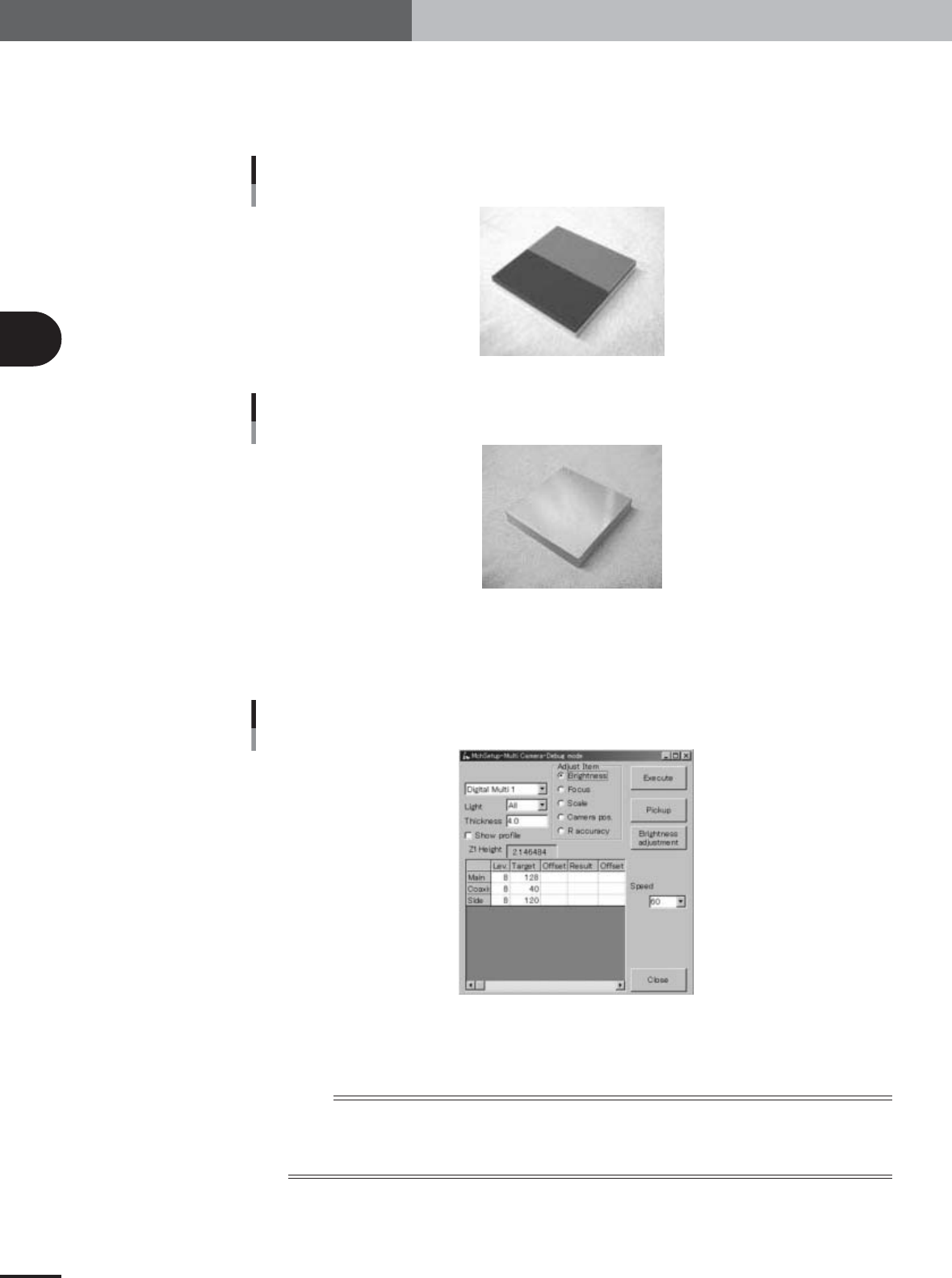
To perform automatic adjustment of the multi-vision camera lighting levels, two custom
tools (light adjuster plate: KM1-M8806-0XX and light adjuster plate-2: KV7-M8806-
0XX) are used. Have these light adjuster plates ready.
Light adjuster plate (KM1-M8806-0XX)
28025-X9-00
Light adjuster plate-2 (KV7-M8806-0XX)
28039-X9-00
1
Press the [Multi Camera] button in the adjustment utility menu
window.
The multi-vision camera adjustment dialog box appears as shown below.
Multi-vision camera adjustment dialog box
27040-X9-00
2
Check that the "Brightness" option button under "Adjust Item" is
selected.
n
NOTE
Also check that other items in the multi-vision camera adjustment dialog box are set as follows.
Light : All
Thickness : 4.0
Speed : 60
3
Basic adjustments
3-11
1. Camera parameter adjustments
3
Press the [Pickup] button in the multi-vision camera adjustment
dialog box.
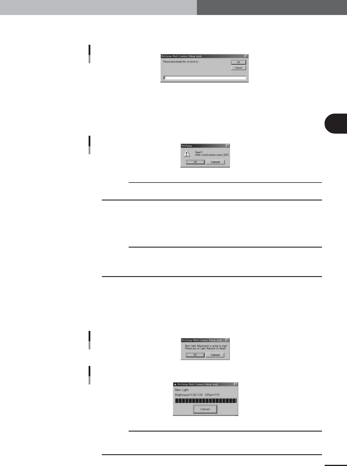
The feeder set No. entry dialog box appears.
Feeder No. entry dialog box
27041-X9-00
4
Specify the pickup position to attach the light adjuster plates to Head
1.
In the feeder set No. entry box, enter the feeder set No. at a position where you can
easily attach the light adjuster plates to Head 1 and then press the [OK] button.
The head assembly will move to the specified pickup position and the confirmation
dialog box appears.
Confirmation dialog box
27042-X9-00
c
CAUTION
If the nozzle of Head 1 is not "Type 74" at this point, then it will be automatically changed to a
Type 74 nozzle.
5
Press the emergency stop button and attach the light adjuster plate to
Head 1.
Attach the light adjuster plate (KM1-M8806-0XX) to Head 1, with the two-tone
surface facing down and the light gray area positioned just under the nozzle tip.
c
CAUTION
The light adjuster plate (KM1-M8806-0XX) is used to adjust the main and coaxial lighting levels,
while the light adjuster plate-2 (KV7-M8806-0XX) is used to adjust the side lighting level.
Adjustments will be made in the order of: the main lighting level, coaxial light level and side
lighting level.
6
Start the main lighting level adjustment.
1.Cancel emergency stop and press the [Execute] button.
The confirmation dialog box appears.
2.Press the [OK] button to start adjustment.
The head assembly moves and passes repeatedly over the multi-vision camera, and
the main lighting level is automatically adjusted.
Start dialog box
27043-X9-00
Progress bar during adjustment
Main light level
27044-X9-00
c
CAUTION
The multi-vision camera adjustments are made automatically. Do not make adjustments in an
environment that greatly differs from the actual production environment. Doing so may lead to
inaccurate data settings, making component recognition unreliable.
e