Xg系列调整手册.pdf - 第70页
3 Basic adjustments 3- 48 3. Head offset adjustments 3.4 Adjusting the head offset of Heads 2, 4, 6 and 8 (YV100Xg family) Follow these steps to adjust the head offset of Heads 2, 4, 6 and 8 (YV100Xg family) using 16-pin…
3
Basic adjustments
3-47
3. Head offset adjustments
q
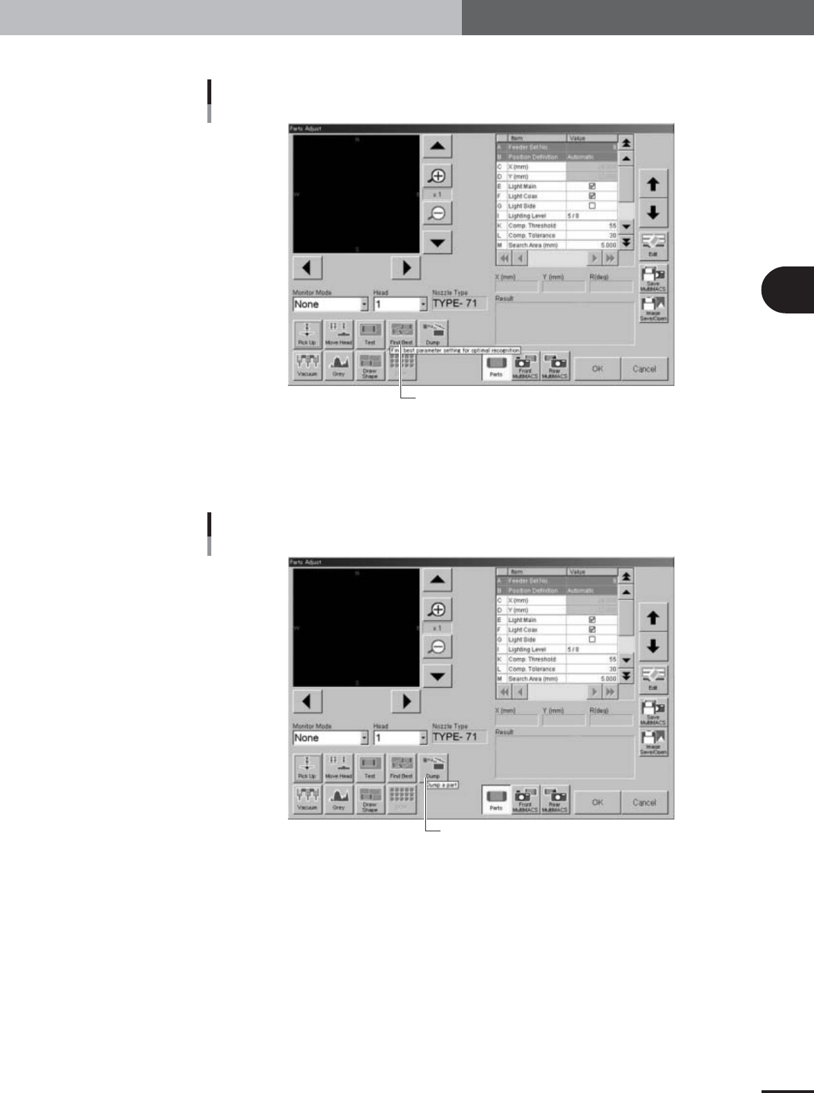
Press the [Find Best] button to find the optimum threshold level.
[Find Best] button
[Find Best] button
27118-X9-00
w
Press the [Dump] button to dump the component.
If you want to manually remove the component from the nozzle, press the emergency
stop and remove it by hand. Then press the [Dump] button to stop the vacuum
suction.
[Dump] button
[Dump] button
27119-X9-00
e
Press the [OK] button to close the Parts Adjust window.
3
Basic adjustments
3-48
3. Head offset adjustments
3.4 Adjusting the head offset of Heads 2, 4, 6 and 8
(YV100Xg family)
Follow these steps to adjust the head offset of Heads 2, 4, 6 and 8 (YV100Xg family)
using 16-pin SOP components.
1
Press the [Utilities] button to start the adjustment utility.
n
NOTE
For how to start the adjustment utility, see section 2.4 in Chapter 2.
2
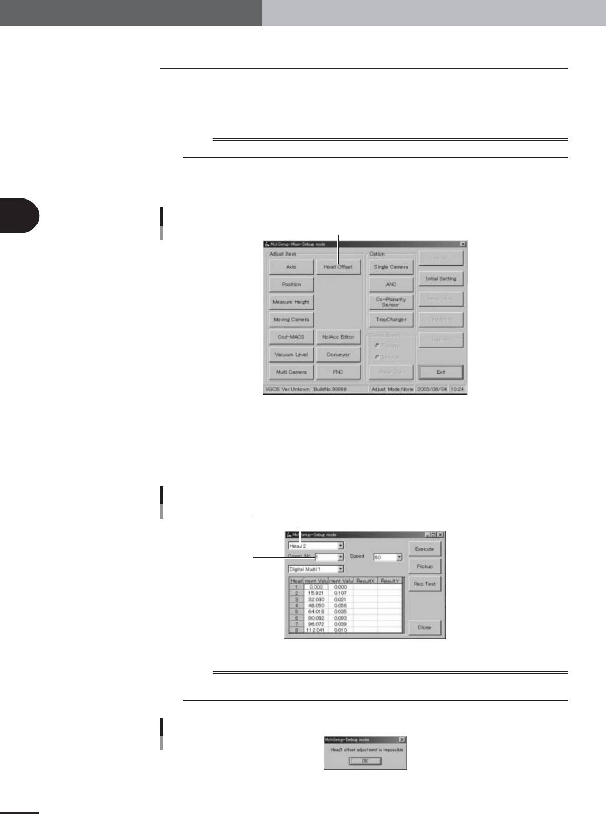
Press the [Head Offset] button to open the head offset adjustment
dialog box.
Adjustment utility menu window
[Head Offset] button
27021-X9-G0
3
Select the adjustment conditions.
Head : Head 2, 4, 6 or 8
Comp. No. : 6 (16-pin SOP)
Camera : Digital Multi 1
Speed : 60
Head offset adjustment dialog box
Enter "11" in the Comp. No. combo box
Select "Head 3", "Head 5" or "Head 7" (YV100Xg family), or "Head 2" (YV88Xg)
27108-X9-00
n
NOTE
Head 1 cannot be selected for head offset adjustment since Head 1 is the reference position. If you select Head 1,
an alert message appears as shown below.
Alert message when Head 1 is selected
27109-X9-00
3
Basic adjustments
3-49
3. Head offset adjustments
4
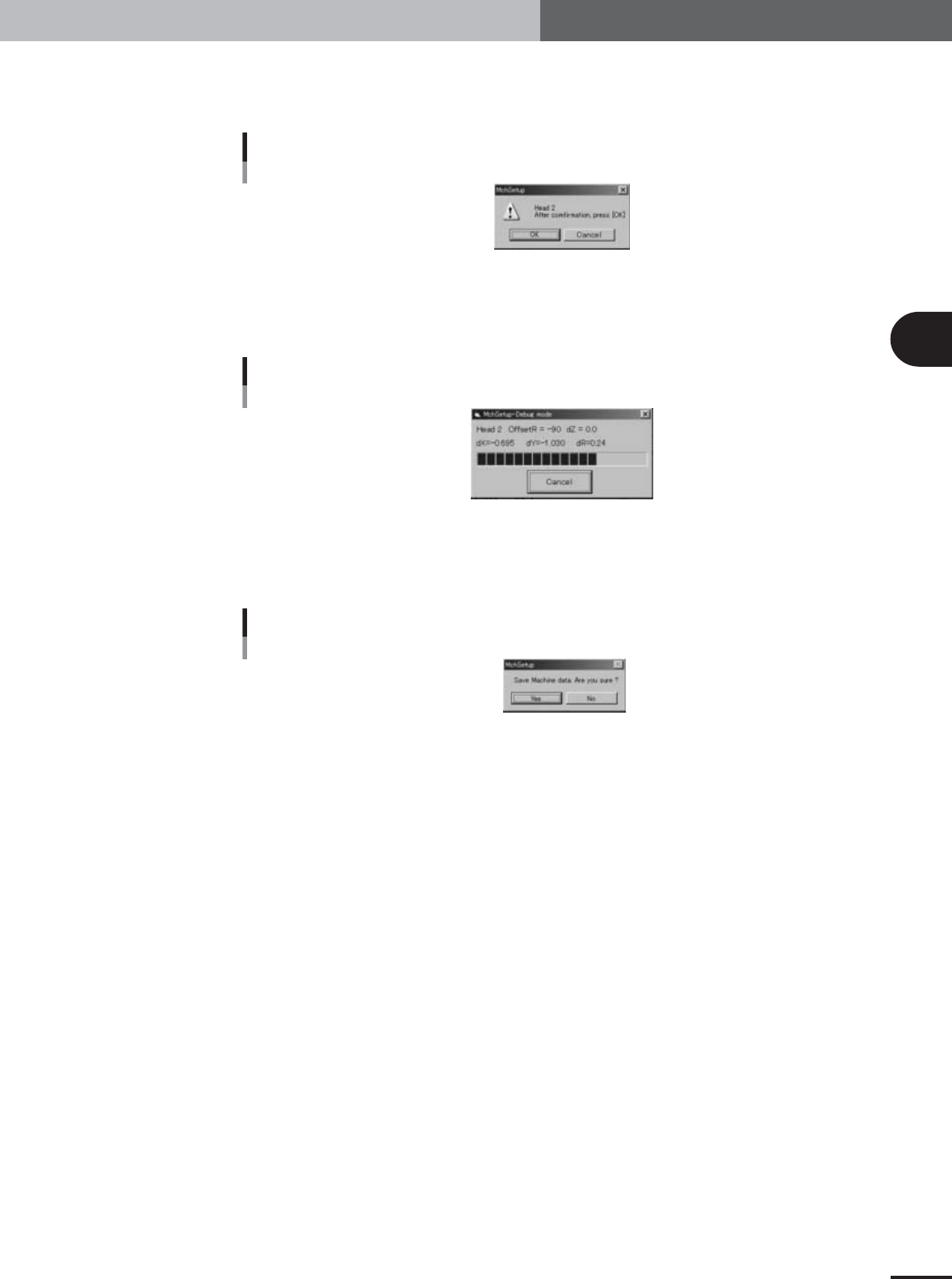
Press the [Execute] button in the head offset adjustment dialog box.
When the dialog box for component pickup appears, press the [OK] button. The head
assembly moves to pick up a component and the confirmation dialog box appears.
Confirmation dialog box
27110-X9-00
5
Press the [OK] button to start the adjustment.
The head assembly moves and passes repeatedly over the multi-vision camera and the
head offset is automatically measured.
Progress bar during adjustment
27111-X9-00
6
Save the result of the head offset adjustment.
When the dialog box appears asking whether to save the result, press the [Yes] button
to save it.
Save confirmation dialog box
27112-X9-00
7
Continue the adjustments of other heads.
When the dialog box appears for dumping the component, press the [OK] button to
continue the adjustments. Select the head you want to next adjust and repeat the
same procedure.