Xg系列调整手册.pdf - 第71页
3 Basic adjustments 3- 49 3. Head offset adjustments 4 Press the [Execute] button in the head offset adjustment dialog box. When the dialog box for component pickup appears, press the [OK] button. The head assembly moves…
3
Basic adjustments
3-48
3. Head offset adjustments
3.4 Adjusting the head offset of Heads 2, 4, 6 and 8
(YV100Xg family)
Follow these steps to adjust the head offset of Heads 2, 4, 6 and 8 (YV100Xg family)
using 16-pin SOP components.
1
Press the [Utilities] button to start the adjustment utility.
n
NOTE
For how to start the adjustment utility, see section 2.4 in Chapter 2.
2
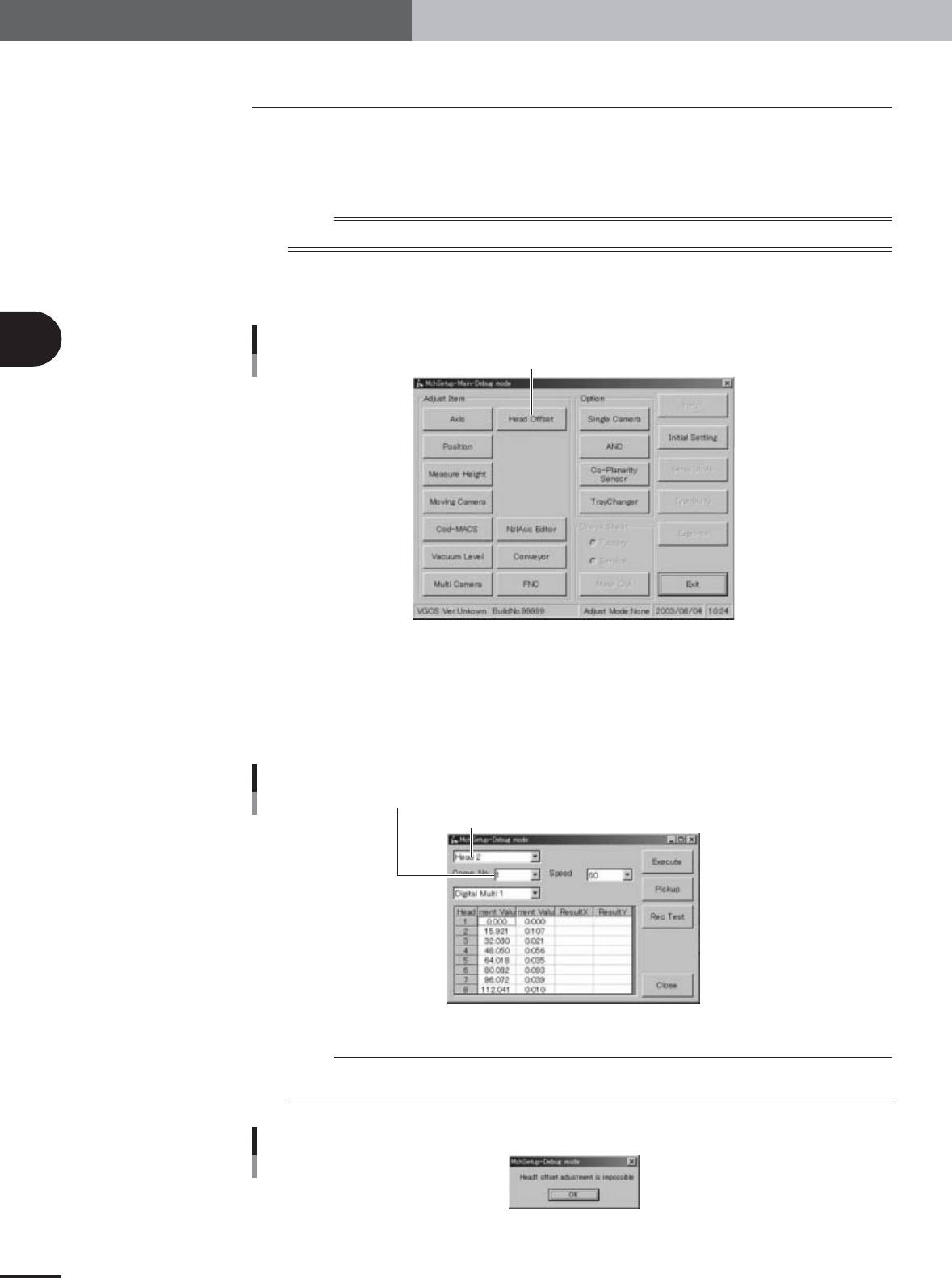
Press the [Head Offset] button to open the head offset adjustment
dialog box.
Adjustment utility menu window
[Head Offset] button
27021-X9-G0
3
Select the adjustment conditions.
Head : Head 2, 4, 6 or 8
Comp. No. : 6 (16-pin SOP)
Camera : Digital Multi 1
Speed : 60
Head offset adjustment dialog box
Enter "11" in the Comp. No. combo box
Select "Head 3", "Head 5" or "Head 7" (YV100Xg family), or "Head 2" (YV88Xg)
27108-X9-00
n
NOTE
Head 1 cannot be selected for head offset adjustment since Head 1 is the reference position. If you select Head 1,
an alert message appears as shown below.
Alert message when Head 1 is selected
27109-X9-00
3
Basic adjustments
3-49
3. Head offset adjustments
4
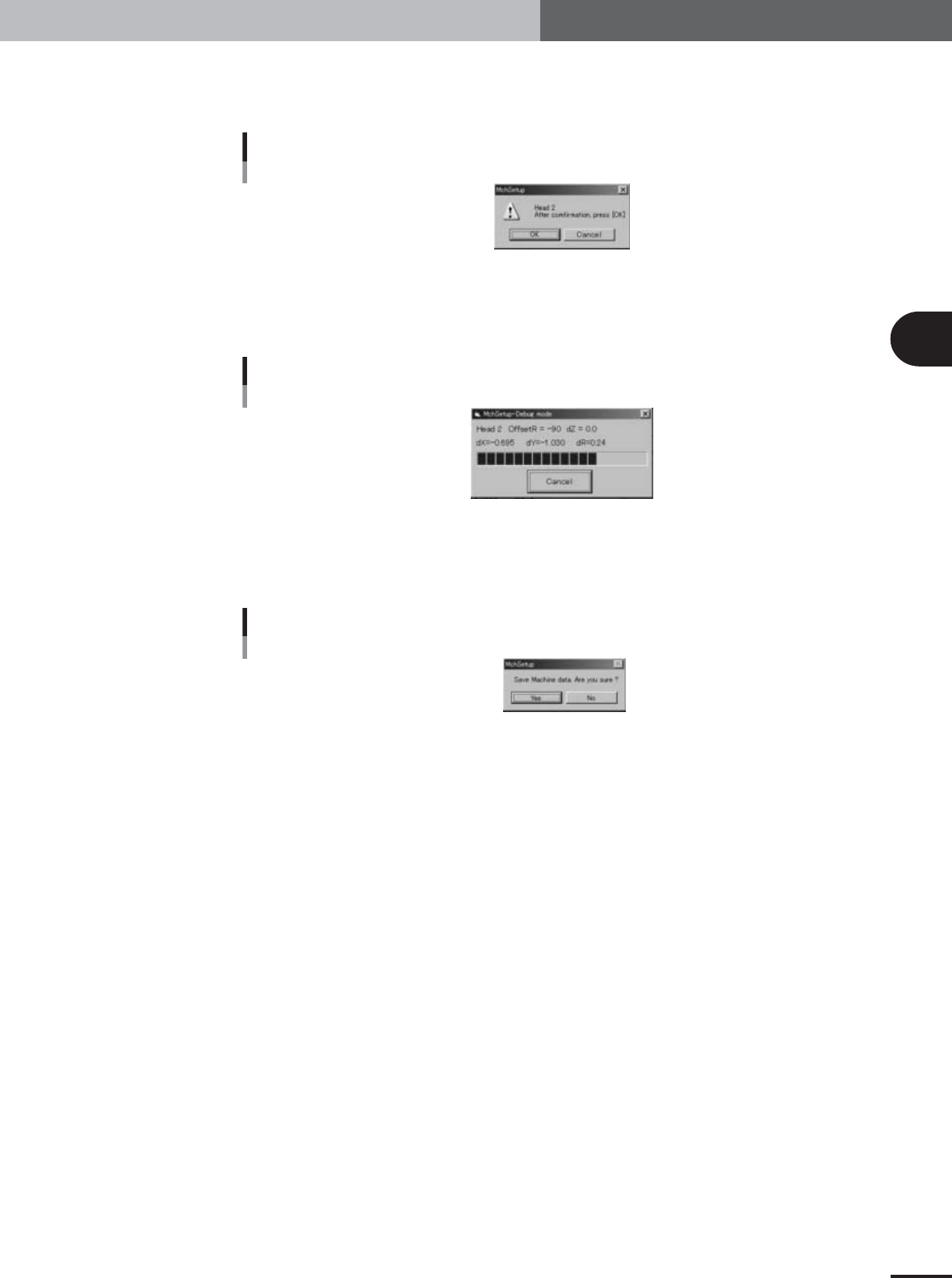
Press the [Execute] button in the head offset adjustment dialog box.
When the dialog box for component pickup appears, press the [OK] button. The head
assembly moves to pick up a component and the confirmation dialog box appears.
Confirmation dialog box
27110-X9-00
5
Press the [OK] button to start the adjustment.
The head assembly moves and passes repeatedly over the multi-vision camera and the
head offset is automatically measured.
Progress bar during adjustment
27111-X9-00
6
Save the result of the head offset adjustment.
When the dialog box appears asking whether to save the result, press the [Yes] button
to save it.
Save confirmation dialog box
27112-X9-00
7
Continue the adjustments of other heads.
When the dialog box appears for dumping the component, press the [OK] button to
continue the adjustments. Select the head you want to next adjust and repeat the
same procedure.
Dig1 Confirmation Dig2 Confirmation
Dig1 Confirmation Dig2 Confirmation
Dig1 Confirmation Dig2 Confirmation
Analog camer
a
Confirmation check
Analog camer
a
Confirmation check
Analog camer
a
Confirmation check
Dig1 Confirmation Dig2 Confirmation
Analog camera1
Analog camera1
Analog camera1
YAMAHA MOTOR Co., Ltd IM Company Service Dept. V1.31(02/02/06)
5
C
onfirmation Check TYPE 71
C
onfirmation Check TYPE 72
C
onfirmation Check TYPE 73
Basic
Adjustment
Machine leveling
Measured on Machine Base
Space to the both sides
of Next machines
Measured the distance
between Pre./Next machines
<=5mm
71 High-Low>40
72 High-Low>70
73 High-Low>100
74 High-Low>130
Pick up/Mount
level
Pre.
mm
C
onfirmation Check TYPE 74
YV100Xg-S / YV100Xg-F
Y
V - R
[ ] Digi. Multi1 [ ] Digi Multi2 [ ] Ana. Single1
Date: / /
Run by: Checked by:
YV100Xg Installation Check Sheet(VGOS 1.0) -1-
Customer
Machine Type
S/N
Software Ver.
Camera Config.
Mch Config.
YTF80W(front) / YTF80W(rear) / ATS20 / ATS20H / W-ATS / Non
mm
PCB conveyor height
Measured conveyor height
of Entrance/Exit side
Standards Check/Result
s
X: Y: mm/
m
N
o.
Adjustment Item
Adj. Content
s
Adj./Chk. Metho
d
mm/m
Nextmm
mm
Air resource pressure Adjust to black mark on cover 0.55 mpa(kgf/cm2)
mpa(kgf/cm2)
900mm±10mm Ent. Ext.
1
2
3
4
Main stoppe
r
upstream
400mm
Ext.Ent. Cen
.
Lft/Fix
Rig/Fix
Lft/Mo Rig/Mo
Lighting Level of
Moving Camera
Adjust the black level and lighting level
using
"Light Adjuster" in "Moving camera"
Blk.Lvl 8±
5
VR1,4,5 (BL+35)±1
VR2 (BL+40)±1,
VR3 (BL+7
)
Set the Glass PCB on the conveyor and
measure PCB height using TYPE72 of
head1
Disparity
<=±0.05mm
Moving Camera
Scale
Execute in "Moving Camera"
using Fid mark on GLASS PCB
Mark No1[Mch_Setup], Dist:1.5
10.0<=Scale<=10.6
Angle:0±0.5deg.
R:
X: Y:
"Light Adj.2" :Milky side
Auto Adjust 128±2
Auto Adjust 40±2
Auto Adjust 120±2
Dig2:Y
Dig1:R
Lighting Level of
Single Camera
48.78±0.98(50mmsq.
)
34.18±0.68(35mmsq.)
Cam. Angle:0±1.0deg.
Multi Camera
Scale, Camera
correction
Using Glass QFP68pin
Comp No.11[Mch_Setup], Dist:3
Select "AdjustMode2"
Check "Scale_y", "Cam.Angle",
"Delta Pos.X" and "Delta Pos.Y"
Delta Pos. X<=±15um
Delta Pos. Y<=±15um
"Light Adj." :Bright side of 2 color
"Light Adj." :Write side
Dig1:X Dig2:X
Dig2:R
Dig1:Y
Rate 1±0.018
Angle:180±1.0deg.
Dig1:Y Dig2:Y
78.75±1.6(32mmsq.
)
105.2±2.0(45mmsq.)
127.1±2.0(54mmsq.)
Camera
Adjustment
Adjustment of
mounting accuracy
7
8
10
11
14
9
12
13
15
F. A. M. F.
Refer another sheet
Confirmation Check:
16
PCB Origin
Other
Adjustment
and Checking
Nozzle Change
ANCTEST:10min.
FNCTEST:10min.
No error
Discard Point
Feeder Plate Offset
Teaching "Locate Pin" in "Position"
Confirmation Check:
Teach using "Feeder Master Jig"
Confirmation Check:
Confirmation Check:
Attach and Teach "Discard Box"
Confirmation Check:
Confirmation Check:
Signal Check;
No impact to
sto
pp
e
r
PCB transfer check:
Pre. Signal
Next Signal
System data back up
and Auto Mount data
Save the System Data after Adjustment
Confirmation Check:
Confirmation Check:
Change back the setting
Back the setting of "AdjustMode"
20
19
17
18
21
22
23
Recordin
g
Line PCB
tarnsport
Execute the dry run and
check the PCB transfer and signal
<=±0.1mm/m
6
Conveyor Width
PCB height
Conveyor
Checking
Measure actual conveyor width
of Ent., Center and Exit side using calipers
approximately
170+0.5mm
Execute in "Vacuum level" for each
nozzle at each head
Set the Glass PCB on the conveyor
and check the gap using scale
approximately
0.5mm
"Light Adj." :Write side
Auto Adjust 40±2
Lighting Level of
Multi Camera
"Light Adj." :Bright side of 2 color
Auto Adjust 128±2
"Light Adj.2" :Milky side
Auto Adjust 120±2
Single Camera
Scale
Using Glass QFP68pin
Comp No.11, Dist:1/10 of F.O.V
Select "AdjustMode2"
Check "Scale_x", "Scale_y",
"Cam.posr" and "Rate"
Mu
l
t
i
Camera Camer
a
Pos.
Execute"Camera Pos." in "Multi camera
"
using Glass QFP68 pin
Execute this command
Head Offset
Execute "Head Offset" for head 2 to 8.using SO
P
Com
p
No.6 in
[
Mch Setu
p]
on multi camera 1
Execute this command
Confirmation check on Multi cam.1
Black Level
VR1-5 Confirmation Check