Xg系列调整手册.pdf - 第47页
3 Basic adjustments 3- 25 1. Camer a parameter adjustments 1.2.3 Calibrating the multi-vision camera scale When calibrating the multi-vision camera scale, a glass QFP specially designed for machine adjustment is used. Ha…
3
Basic adjustments
3-24
1. Camera parameter adjustments
1.2.2 Calibrating the moving camera scale
1
Press the [Utilities] button to start the adjustment utility.
n
NOTE
For how to start the adjustment utility, see section 2.4 in Chapter 2.
2
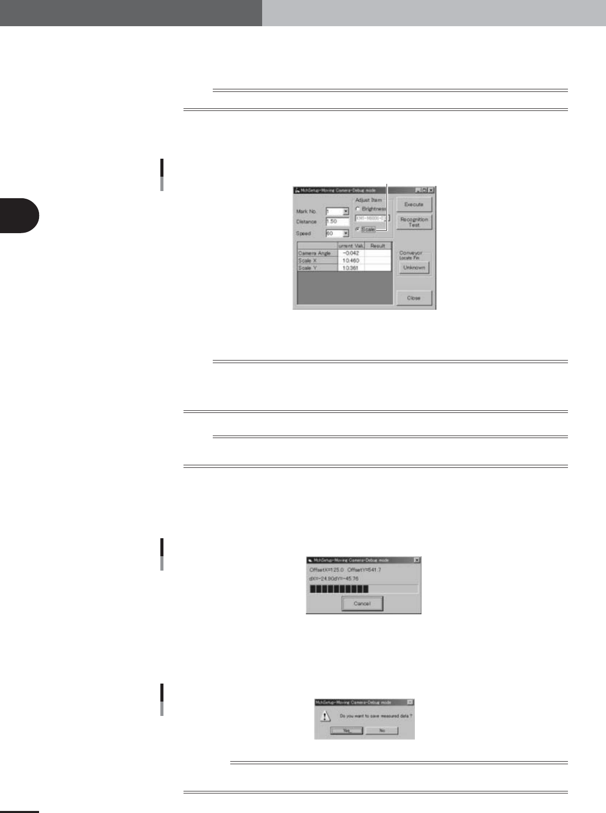
Press the [Moving Camera] button to open the moving camera
adjustment dialog box.
Moving camera adjustment dialog box
Select the "Scale" option button
27077-X9-00
3
Select the "Scale" option button under "Adjust Item".
n
NOTE
Also check that other items in the above dialog box are set as follows.
Mark No. : 1
Distance : 1.50
Speed : 60
n
NOTE
You do not have to execute a vision test with the [Recognition Test] button since the optimum threshold level has
already been obtained in the previous section.
4
Press the [Execute] button to start calibration.
The moving camera moves along the X and Y axes and the camera scale is automati-
cally calibrated based on the amount of movement on the vision monitor and the
results are then displayed on the screen.
Progress bar during adjustment
27078-X9-00
5
Save the result of the camera scale calibration.
When the dialog box appears asking whether to save the result, press the [Yes] button
to save it.
Save confirmation dialog box
27080-X9-00
Reference
Typical moving camera scale: 10.3±0.3 µ m/pixel
Typical camera installation angle: 0±0.5°
3
Basic adjustments
3-25
1. Camera parameter adjustments
1.2.3 Calibrating the multi-vision camera scale
When calibrating the multi-vision camera scale, a glass QFP specially designed for
machine adjustment is used. Have the glass QFP ready before beginning calibration.
1
Check the "Adjust Mode" parameter and PCB data.
Calibration of the multi-vision camera scale uses a glass QFP, so the machine must be
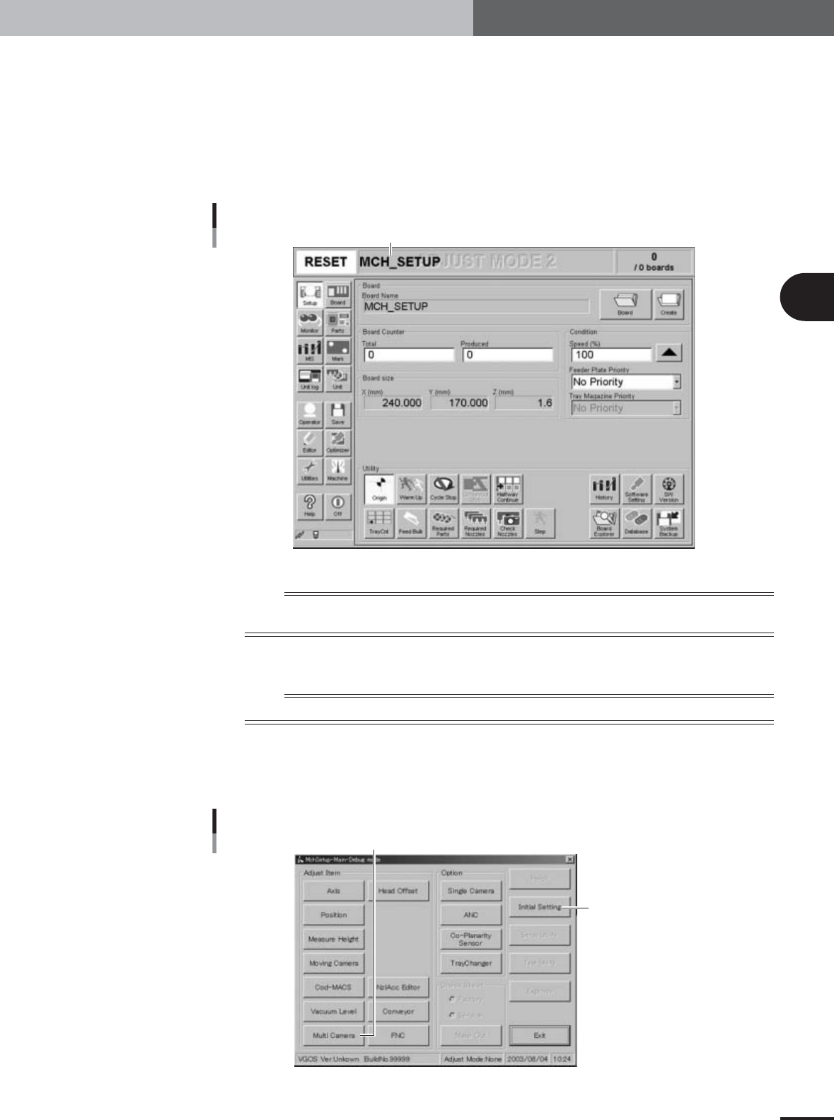
set to "Adjust Mode2" and the "MCH_SETUP" PCB data loaded into the machine.
You can check the currently selected PCB data and "Adjust Mode" on the status bar.
Status bar display
Status bar shows currently selected PCB data and "Adjust Mode".
27085-X9-00
n
NOTE
To calibrate the multi-vision camera scale, the machine must be set to "Adjust Mode2" (see sections 2.5 and 2.6
in Chapter 2) and the "MCH_SETUP" PCB data loaded into the machine (see section 2.7 in Chapter 2).
2
Press the [Utilities] button to start the adjustment utility.
n
NOTE
For how to start the adjustment utility, see section 2.4 in Chapter 2.
3
Press the [Multi Camera] button in the adjustment utility menu
window.
The multi-vision camera adjustment dialog box appears.
Adjustment utility menu window
[Multi Camera] button
The Adjust Mode parameter can
also be changed using this button.
27021-X9-C0
3
Basic adjustments
3-26
1. Camera parameter adjustments
4
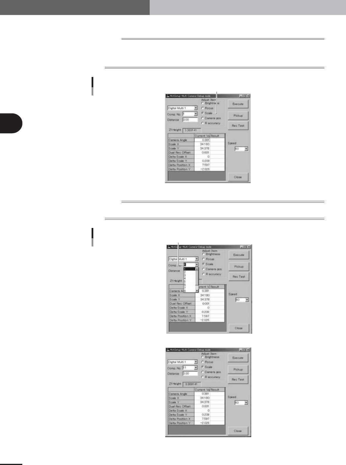
Select the "Scale" option button under "Adjust Item".
n
NOTE
Also check that other items in the multi-vision camera adjustment dialog box are set as follows.
Camera : Digital Multi 1 or 2
Comp. No. : 11 (glass QFP)
Distance : 3.00
Multi-vision camera adjustment dialog box
Select the "Scale" option button.
27087-X9-00
n
NOTE
Only numbers up to 10 are selectable from the drop-down list of the "Comp. No." combo box, so enter "11" from
the keyboard. In the "MCH_SETUP" PCB data, component No.11 is assigned to glass QFP (KMO-M880A-202).
Component No. combo box
Enter "11".
27088-X9-00
27089-X9-00