Xg系列调整手册.pdf - 第52页
3 Basic adjustments 3- 30 1. Camer a parameter adjustments Component No. combo box Enter "11". 27095-X9-00 27096-X9-00 5 Press the [Pickup] button in the single-vision camera adjustment dialog box. The head ass…
3
Basic adjustments
3-29
1. Camera parameter adjustments
2
Press the [Utilities] button to start the adjustment utility.
n
NOTE
For how to start the adjustment utility, see section 2.4 in Chapter 2.
3
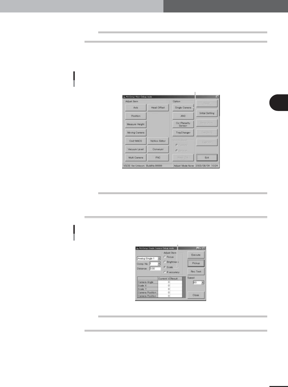
Press the [Single Camera] button in the adjustment utility menu
window.
The single-vision camera adjustment dialog box appears.
Adjustment utility menu window
[Single Camera] button
27021-X9-D0
4
Select the "Scale" option button under "Adjust Item".
n
NOTE
Also check that other items in the single-vision camera adjustment dialog box are set as follows.
Camera : Analog Single 1 or 2
Comp. No. : 11 (glass QFP)
Distance : 3.00
Single-vision camera adjustment dialog box
Select the "Scale" option button.
27094-X9-00
n
NOTE
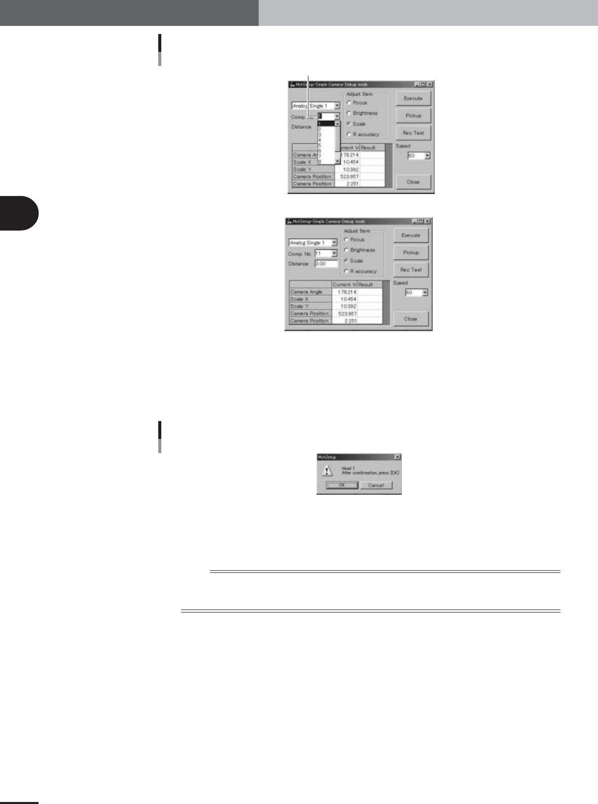
Only numbers up to 10 are selectable from the drop-down list of the "Comp. No." combo box, so enter "11" from
the keyboard. In the "MCH_SETUP" PCB data, component No.11 is assigned to glass QFP (KMO-M880A-202).
3
Basic adjustments
3-30
1. Camera parameter adjustments
Component No. combo box
Enter "11".
27095-X9-00
27096-X9-00
5
Press the [Pickup] button in the single-vision camera adjustment
dialog box.
The head assembly moves to the component pickup position and the confirmation
dialog box appears.
Confirmation dialog box
27097-X9-00
6
Press the emergency stop button and attach the glass QFP to Head 1.
Attach the glass QFP to the nozzle of Head 1, with the pin-pattern-printed surface
facing down (toward the camera), and then press the [OK] button.
n
NOTE
Handle the glass QFP carefully and protect it from dust and grime. Dust, grime or nicks on the glass QFP surface
may cause recognition errors or result in poor adjustment.
Make sure the nozzle picks up the center of the glass QFP.
e
3
Basic adjustments
3-31
1. Camera parameter adjustments
7
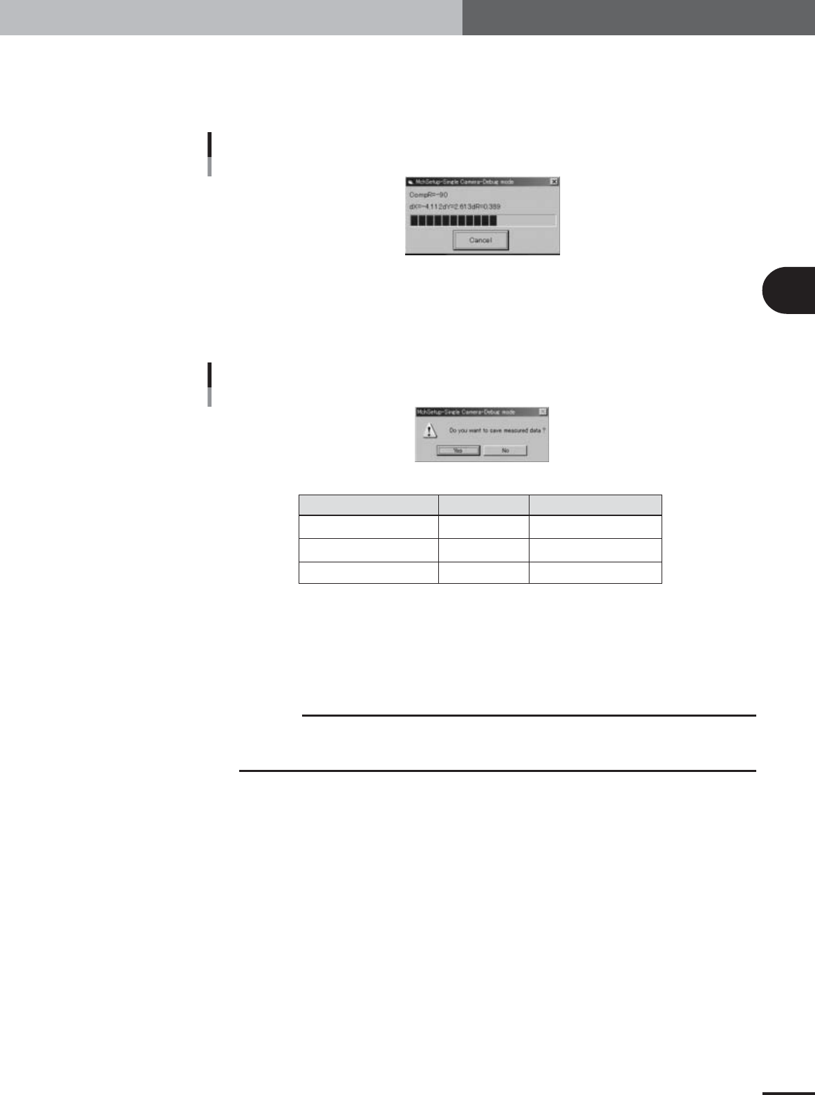
Cancel emergency stop and press the [Execute] button to start
calibration.
The head assembly moves to a position above the single-vision camera and the
camera scale is automatically calibrated.
Progress bar during adjustment
27098-X9-00
8
Check the calibrated results.
When the scale calibration is complete, a dialog box appears asking whether to save
the results. Check that the results are within the typical range (shown in table below)
and press the [Yes] button to enable the results.
Save confirmation dialog box
27099-X9-00
Typical range
Camera with 35x35mm FOV
Camera with 45x45mm FOV
Camera with 50x50mm FOV
XY scale
78.75±1.6µm
105.2±2.0µm
127±2.5µm
Camera installation angle
180±1°
180±1°
180±1°
25007-X9-00
9
Remove the glass QFP from the nozzle.
When the dialog box appears after saving the data, press the emergency stop button
and remove the glass QFP by hand from the nozzle. Then press the [OK] button in the
dialog box.
c
CAUTION
If you press the [OK] button while the glass QFP is still being held by to the nozzle, the glass
QFP will be automatically dumped and possibly damaged. Always first remove the glass QFP by
hand and then press the [OK] button.
e