Dual Simultaneous Programmable Pitch Rev 02.pdf - 第12页
Dual-Simultaneous Pr ogrammable Pitch Owner ’s Manual In stallation and Configuratio n 8 © 2024 No rdson Corpor ation 3.5 Adjusting Limit Sensor To adjust the limit sensor ( Fi gure 3 -1): 1. Loosen the two (2) scr ews o…
© 2024 Nordson Corporation 7
3 Installation and Configuration
3.1 Overview
The DSPP should come already installed and configured for your conformal coating system. The DSPP
may need minor adjustments from time to time, or after changing applicators. This section includes the
following instructions:
•
Adjusting Limit Sensor
•
Adjusting Y
-
•
Adjusting Applicator Height
•
Third Valve Option
•
Adjusting Applicator Pitch
3.2 Safety First
Operation of the Dual-Simultaneous Programmable Pitch involves mechanical devices and electrical
power. It is essential that every person servicing or operating the DSPP fully understands all hazards,
risks, and safety precautions. See Section 2 - Safety for additional information.
WARNING!
Allow only qualified personnel to perform the following tasks. Follow the safety
instructions in this document and all other related documentation.
WARNING!
Ensure the fluid system is completely depressurized prior to loosening any fittings
in the fluid path. Failure to do so may cause serious injury to personnel.
3.3 Tools and Materials Needed
• Torque Wrench
• Metric Hex Key Set
3.4 Unpacking the DSPP
Every care has been taken when packaging the DSPP. However, we recommend that you look for
obvious damage and verify contents against the packing slip.
Retain the case for storage of the DSPP and accessories. Retain shipping cartons for future use. If an
item needs to be returned to Nordson, obtain a Return Material Authorization (RMA) number from
Nordson, see 7.3 Parts Ordering Information.
Dual-Simultaneous Programmable Pitch Owner’s Manual Installation and Configuration
8 © 2024 Nordson Corporation
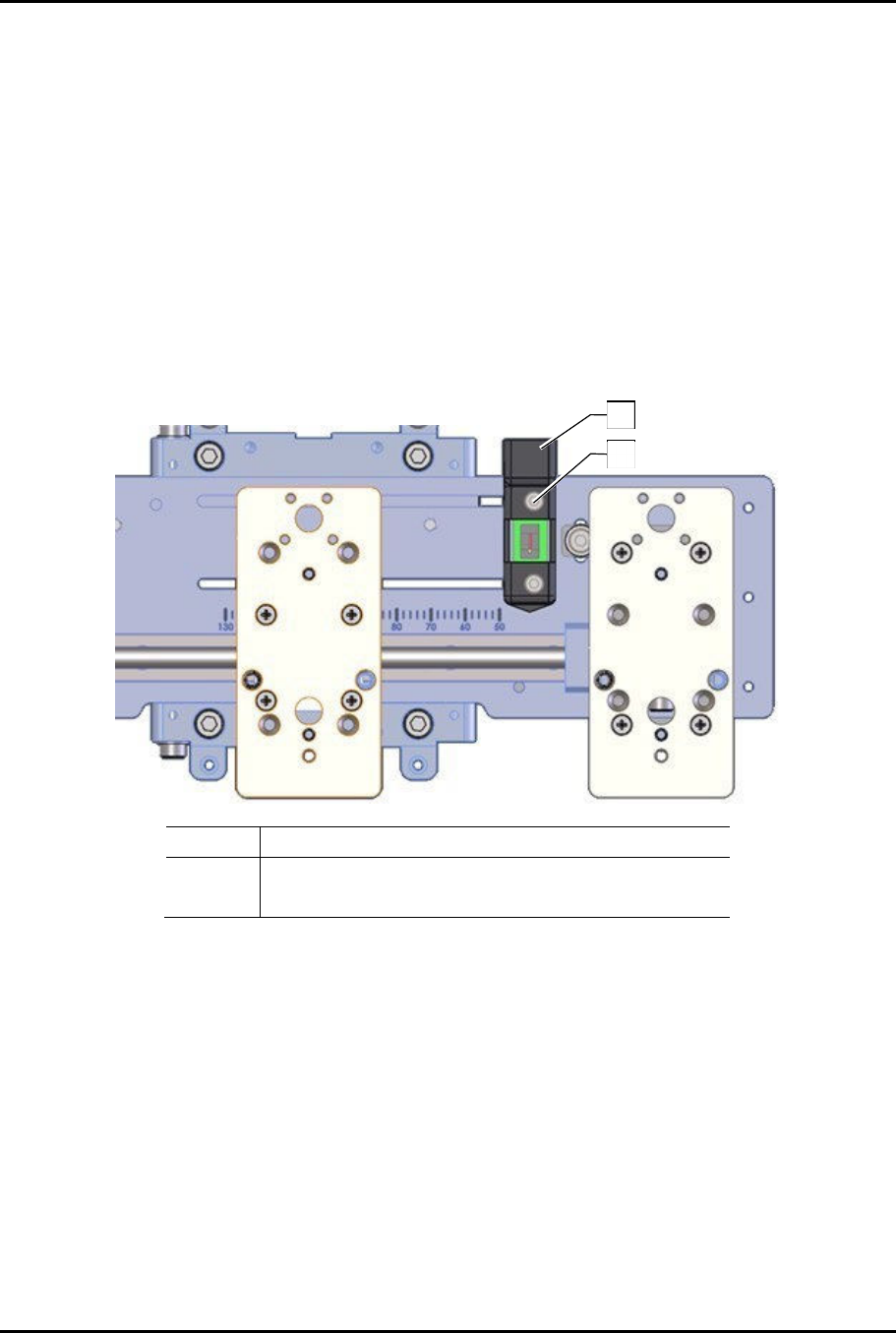
3.5 Adjusting Limit Sensor
To adjust the limit sensor (Figure 3-1):
1. Loosen the two (2) screws on the front of the limit sensor.
?
NOTE
There are nuts on the back of each screw. Do not loosen the screws too much or
the nuts will off.
2. Slide the limit sensor to the appropriate position, depending on which applicator is
configured for the coating system, see Table 1-1.
3. Tighten the two (2) screws on the front of the limit sensor.
?
NOTE
The limit sensor may need to be adjusted after installing the applicator to prevent
applicators from colliding when traveling to the narrowest pitch.
Item Description
1 Limit Sensor
2 Screws (2)
Figure 3-1 Position Limit Sensor
1
2

Dual-Simultaneous Programmable Pitch Owner’s Manual Installation and Configuration
© 2024 Nordson Corporation 9
3.6 Adjusting Applicator Height
?
NOTE
Applicators should be at the same height. Applicator height is changed by adjusting
the height of the applicator bracket.
To adjust applicator height (Figure 3-2):
?
NOTE
The height adjustment screws must be used in conjunction. Do not tighten one without
loosening the other. When finished, the height adjustment screws and side setscrew
must be tight against pivot.
1. Install the applicable applicators, refer to the applicable applicator manuals.
WARNING!
When installing, performing maintenance, or making adjustments with power on,
do not hot swap the Pitch Motor and Pitch ENC and Sensors cables on the
Z-head (Figure 3-5).
2. Loosen, do not remove, the side setscrew.
3. To raise the applicator bracket, loosen the bottom height adjustment screw and tighten the
top height adjustment screw.
4. To lower the applicator bracket, loosen the top height adjustment screw and tighten the
bottom height adjustment screw.
5. Tighten the side setscrew.