Dual Simultaneous Programmable Pitch Rev 02.pdf - 第14页
Dual-Simultaneous Pr ogrammable Pitch Owner ’s Manual In stallation and Configuratio n 10 © 2024 Nordson Corporation Top Height Ad justment Screw Bottom Height Adjustment Scr ew Item Description Item Description 1 Top He…

Dual-Simultaneous Programmable Pitch Owner’s Manual Installation and Configuration
© 2024 Nordson Corporation 9
3.6 Adjusting Applicator Height
?
NOTE
Applicators should be at the same height. Applicator height is changed by adjusting
the height of the applicator bracket.
To adjust applicator height (Figure 3-2):
?
NOTE
The height adjustment screws must be used in conjunction. Do not tighten one without
loosening the other. When finished, the height adjustment screws and side setscrew
must be tight against pivot.
1. Install the applicable applicators, refer to the applicable applicator manuals.
WARNING!
When installing, performing maintenance, or making adjustments with power on,
do not hot swap the Pitch Motor and Pitch ENC and Sensors cables on the
Z-head (Figure 3-5).
2. Loosen, do not remove, the side setscrew.
3. To raise the applicator bracket, loosen the bottom height adjustment screw and tighten the
top height adjustment screw.
4. To lower the applicator bracket, loosen the top height adjustment screw and tighten the
bottom height adjustment screw.
5. Tighten the side setscrew.
Dual-Simultaneous Programmable Pitch Owner’s Manual Installation and Configuration
10 © 2024 Nordson Corporation
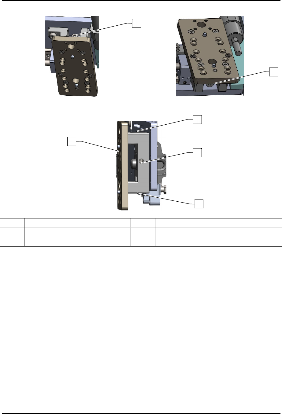
Top Height Adjustment Screw
Bottom Height Adjustment Screw
Item Description Item Description
1 Top Height Adjustment Screw 3 Applicator Bracket
2 Bottom Height Adjustment Screw 4 Side Setscrew
Figure 3-2 Adjust Applicator Height
1
2
3
1
2
4
Dual-Simultaneous Programmable Pitch Owner’s Manual Installation and Configuration
© 2024 Nordson Corporation 11
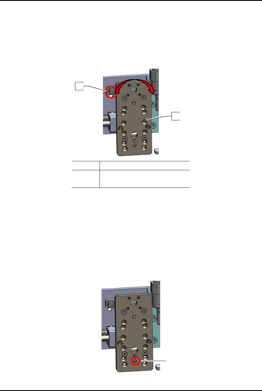
3.7 Adjusting Applicator Pitch
To adjust the applicator pitch (Figure 3-3).
1. Loosen the locking screw.
2. Rotate the applicator bracket by hand to square it to the conveyor rail.
3. Torque the locking screw to 2.82 Nm (25 in-lbs).
Item Description
1 Locking Screw
2 Applicator Bracket
Figure 3-3 Adjust Applicator Pitch
3.8 Adjusting Y-Tilt
To adjust the Y-tilt (Figure 3-4):
1. Identify which applicator needs to be tilted forward.
2. Loosen the two (2) screws attaching the applicator to the bracket.
3. From the back side of the applicator bracket, adjust the setscrew extension, longer or
shorter, as needed.
4. Re-tighten applicator screws.
Figure 3-4 Adjust Y-Axis Alignment
1
2
Setscrew