Dual Simultaneous Programmable Pitch Rev 02.pdf - 第20页
Dual-Simultaneous Pr ogrammable Pitch Owner ’s Manual In stallation and Configuratio n 16 © 2024 Nordson Corporation ? NOTE If the V2 applicator is a l arger dispens ing valve (i.e., S C-280) with ro tate and tilt, the t…
Dual-Simultaneous Programmable Pitch Owner’s Manual Installation and Configuration
© 2024 Nordson Corporation 15
To adjust the X-axis travel:
?
NOTE
If the V1 and V2 applicators are smaller dispensing valves (i.e., SC-300 or SC-400’s),
X-axis travel can be increased by moving the toggle bracket to the inside slot
(Figure 3-7).
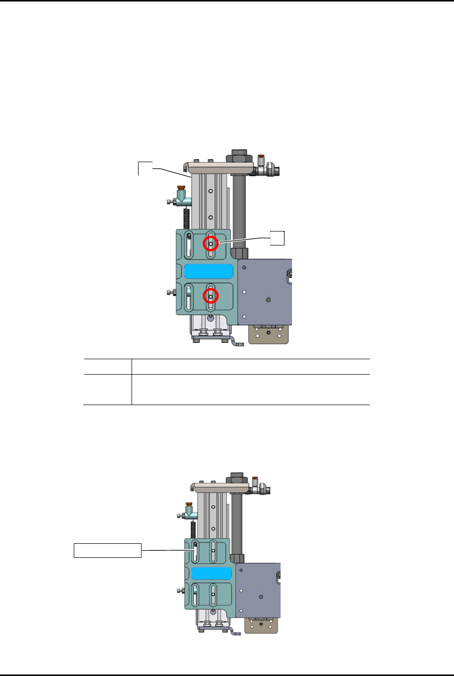
1. Remove the two (2) mounting screws.
2. Move the toggle bracket to the inside slot.
3. Re-install the two (2) mounting screws.
Item Description
1 Toggle Bracket
2 Screws (2)
Figure 3-7 Increasing X-Axis Travel
?
NOTE
If the V2 applicator is a larger dispensing valve (i.e., SC-280) with rotate, the toggle
bracket must be mounted on the outside slot (Figure 3-8).
Figure 3-8 Toggle Bracket on Outside Slot
1
2
Outside slot
Dual-Simultaneous Programmable Pitch Owner’s Manual Installation and Configuration
16 © 2024 Nordson Corporation
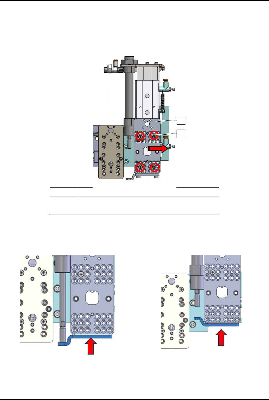
?
NOTE
If the V2 applicator is a larger dispensing valve (i.e., SC-280) with rotate and tilt, the
toggle bracket must be mounted on the outside slot and the applicator bracket on the
front of the toggle bracket must also be moved as far to the right as possible
(Figure 3-9).
Item Description
1 Applicator Bracket
2 Screws (4)
Figure 3-9 Moving Toggle Bracket Applicator Bracket
4. Remove the two (2) screws securing the slide (Figure 3-10).
5. Orient the slide to the desired configuration.
Default Toggle Stop “Down”
(Two Solvent Cups and Ultrasonic Cleaner
Configuration)
Toggle Stop “Up”
(Three Solvent Cups Configuration)
Figure 3-10 Configuring the Slide for the 3rd Applicator
2
1
Dual-Simultaneous Programmable Pitch Owner’s Manual Installation and Configuration
© 2024 Nordson Corporation 17
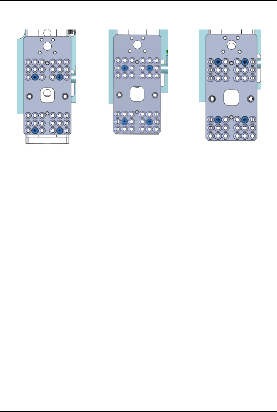
6. To align the applicators and clear the service station, the DSPP mounting plate may need to
change position (Figure 3-11).
UP Position
Center Position (default)
Down Position
Figure 3-11 Toggle Mounting Plate Positions