Dual Simultaneous Programmable Pitch Rev 02.pdf - 第18页
Dual-Simultaneous Pr ogrammable Pitch Owner ’s Manual In stallation and Configuratio n 14 © 2024 Nordson Corporation 3.9.2 Adjustin g Third Valve Option The DSPP with the t hird valv e option can be adjus ted to acc ommo…
Dual-Simultaneous Programmable Pitch Owner’s Manual Installation and Configuration
© 2024 Nordson Corporation 13
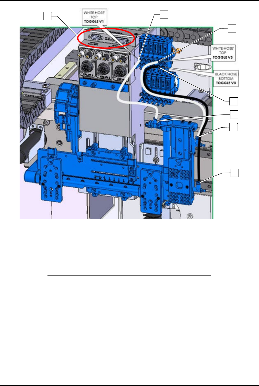
Item Description
1
Pitch Motor and Pitch ENC and Sensors
Connections (DO NOT HOT SWAP)
2 Toggle V1 Top Connection (White Tubing)
3 Toggle V3 Top Connection (White Tubing)
4 Toggle V3 Bottom Connection (Black Tubing)
Figure 3-5 Third Valve Option
4
3
3
3
4
2
1
Dual-Simultaneous Programmable Pitch Owner’s Manual Installation and Configuration
14 © 2024 Nordson Corporation
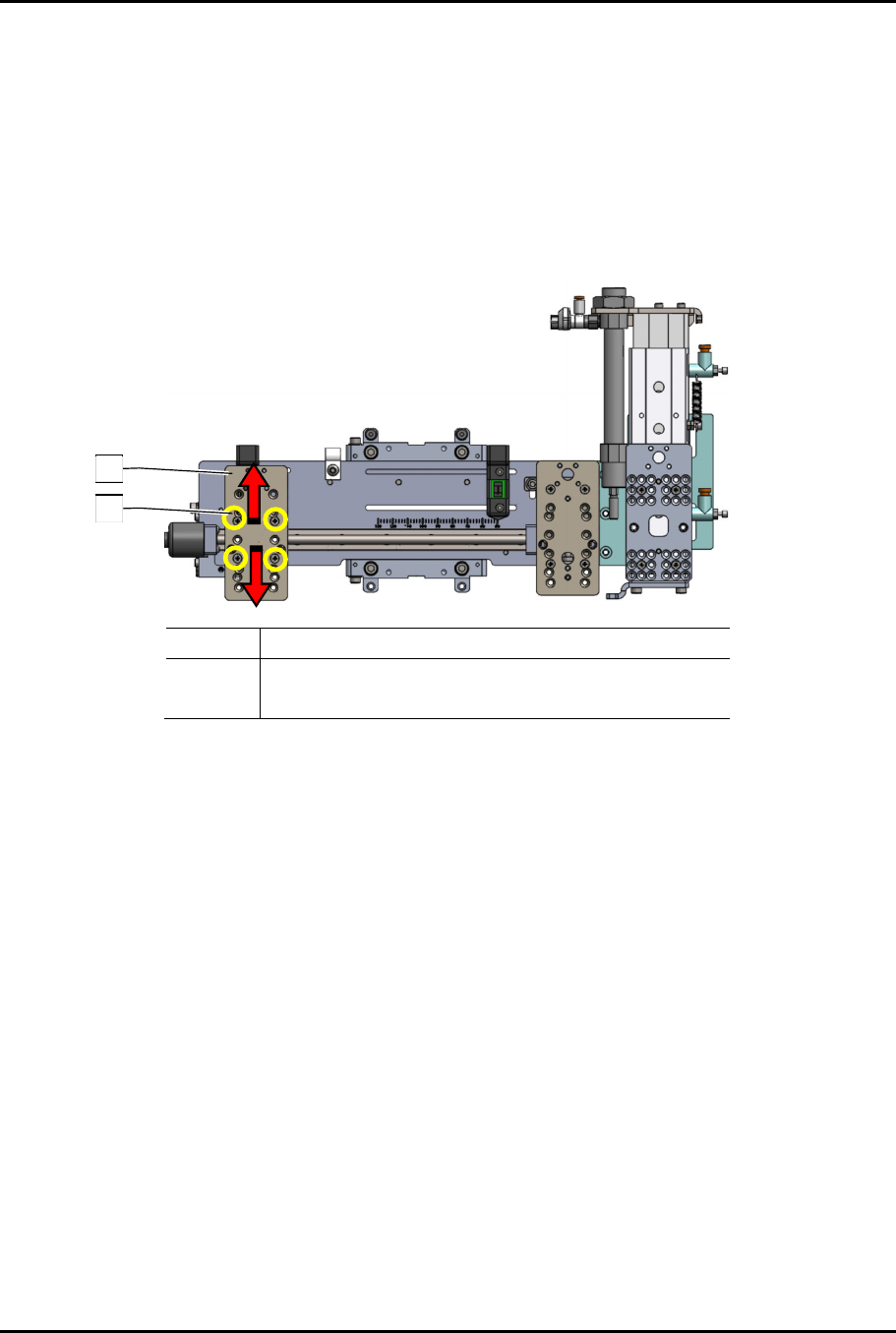
3.9.2 Adjusting Third Valve Option
The DSPP with the third valve option can be adjusted to accommodate any valve combination.
To adjust the V1 and V2 Z height (Figure 3-6):
1. Remove the four (4) screws holding the applicator bracket.
2. Move the applicator bracket up or down to the desired height.
3. Re-install the four (4) screws.
Item Description
1 Applicator Bracket
2 Screws (4)
Figure 3-6 Adjusting V1 and V2 Z Height
1
2
Dual-Simultaneous Programmable Pitch Owner’s Manual Installation and Configuration
© 2024 Nordson Corporation 15
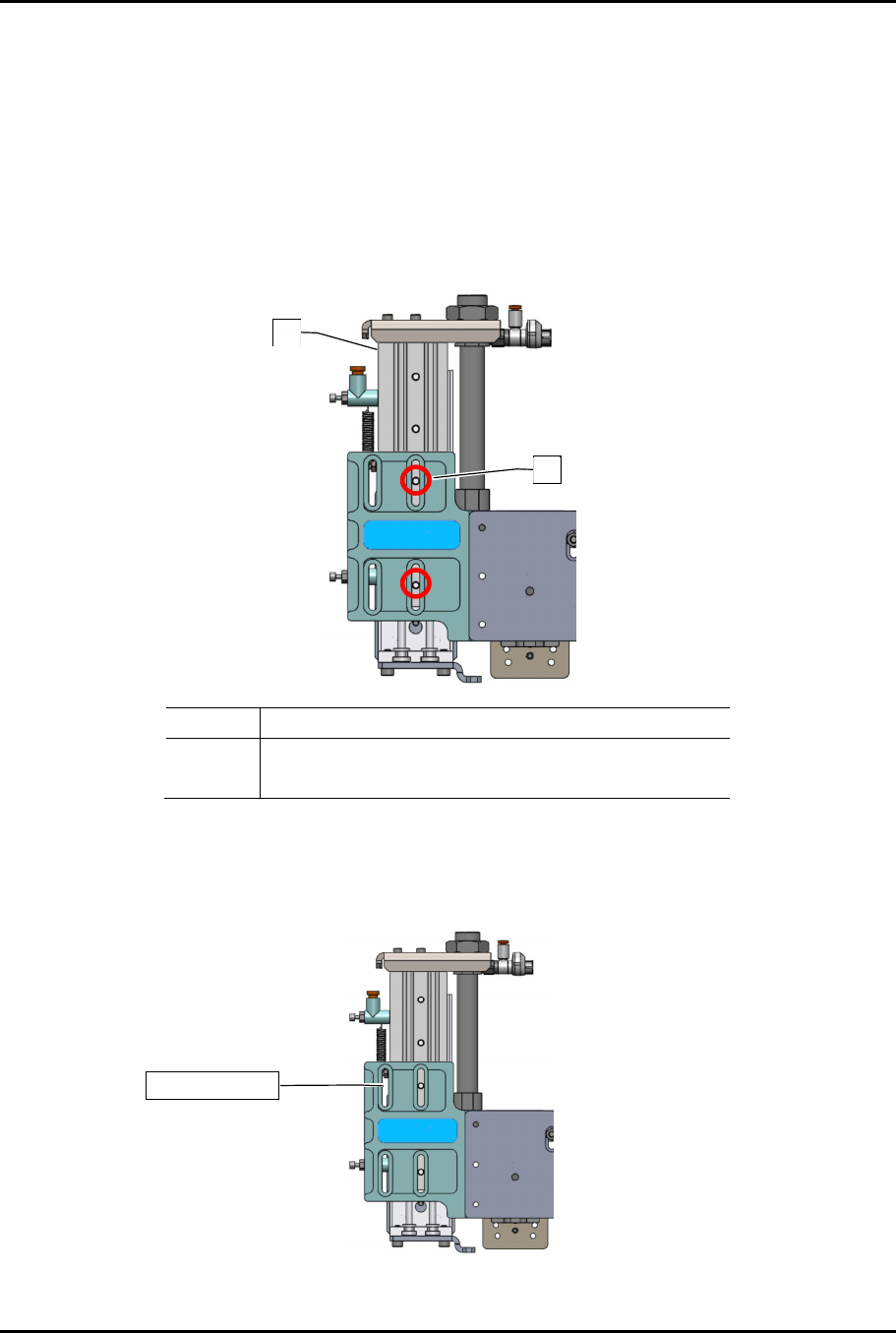
To adjust the X-axis travel:
?
NOTE
If the V1 and V2 applicators are smaller dispensing valves (i.e., SC-300 or SC-400’s),
X-axis travel can be increased by moving the toggle bracket to the inside slot
(Figure 3-7).
1. Remove the two (2) mounting screws.
2. Move the toggle bracket to the inside slot.
3. Re-install the two (2) mounting screws.
Item Description
1 Toggle Bracket
2 Screws (2)
Figure 3-7 Increasing X-Axis Travel
?
NOTE
If the V2 applicator is a larger dispensing valve (i.e., SC-280) with rotate, the toggle
bracket must be mounted on the outside slot (Figure 3-8).
Figure 3-8 Toggle Bracket on Outside Slot
1
2
Outside slot