Dual Simultaneous Programmable Pitch Rev 02.pdf - 第52页
Dual-Simultaneous Pr ogrammable Pitch Owner ’s Manual Operation 48 © 2024 Nordson Corporation Figure 4-54 Click Finish 35. In Tool Configurat ion, selec t Applicator Right an d click on Configu re . Figure 4-55 Sw itch t…
Dual-Simultaneous Programmable Pitch Owner’s Manual Operation
© 2024 Nordson Corporation 47
30. Once the stipes have been dispensed, EasyCoat will display the results (Figure 4-52).
Figure 4-52 Dispensing Results
31. Click Next.
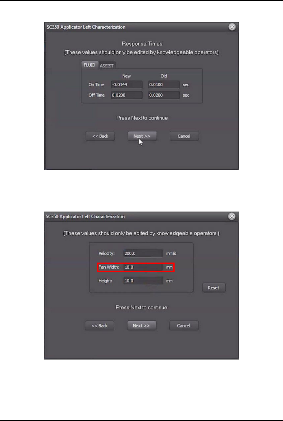
32. Change Fan Width to 10 mm (Figure 4-53).
Figure 4-53 Change Fan Width
33. Click Next.
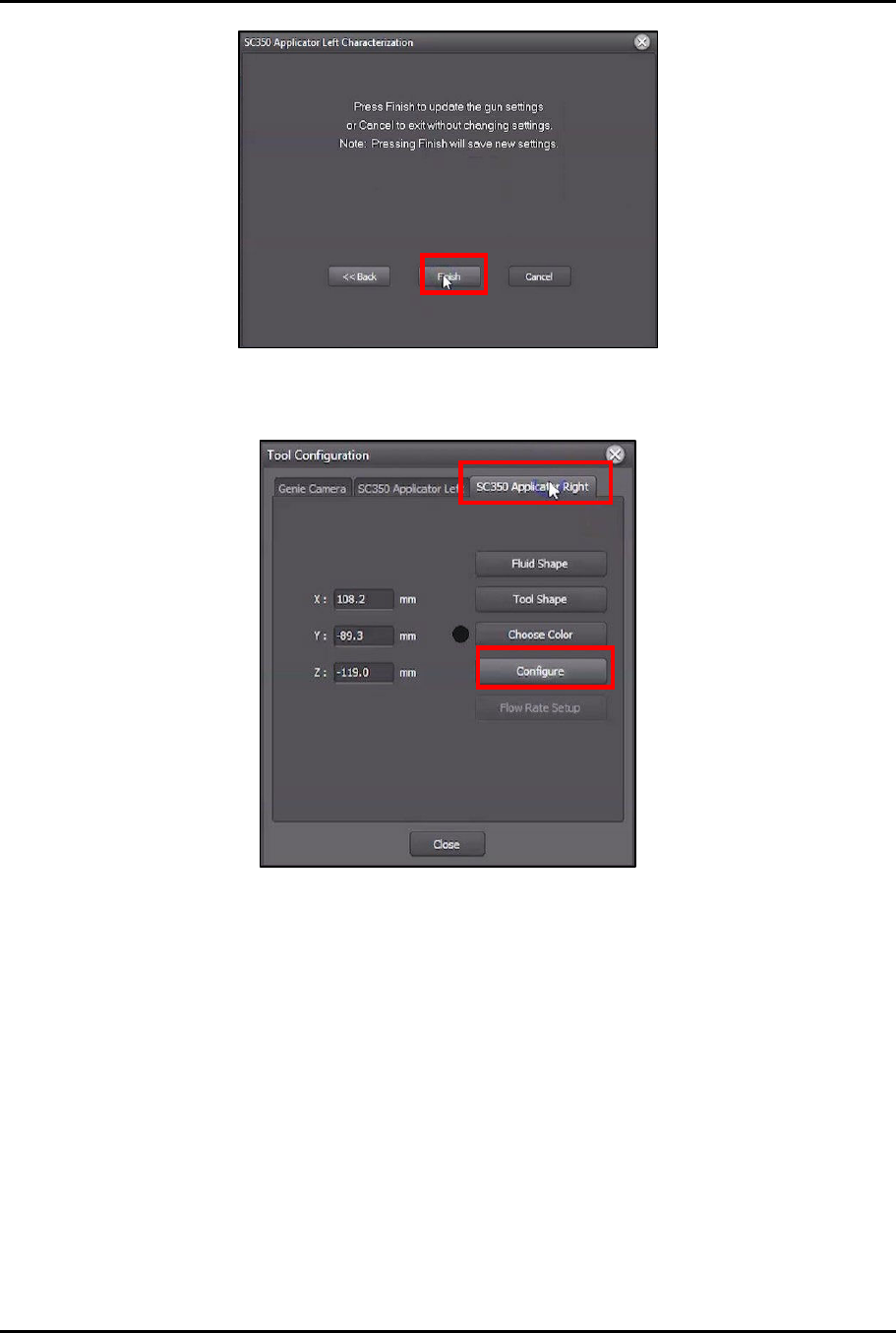
34. Click Finish to update the settings (Figure 4-54).
Dual-Simultaneous Programmable Pitch Owner’s Manual Operation
48 © 2024 Nordson Corporation
Figure 4-54 Click Finish
35. In Tool Configuration, select Applicator Right and click on Configure.
Figure 4-55 Switch to Applicator Right
36. Perform Step 9 through Step 34 of this procedure to complete the characterization process
for the right valve.
?
NOTE
Make sure that all the valve settings used for the right valve are the same
settings that were used for the left valve.
37. Compare the results of the characterization cards side by side and adjust the parameters of
the second valve until the results of the second valve match the results of the first valve as
closely as possible.
?
NOTE
If a Qadence system is installed, ensure that the flow rate is the same for each
valve.
?
NOTE
If a laser fan width system is installed, ensure that the fan width settings are the
same for each valve.
38. Repeat this procedure until the results for each valve match as closely as possible.
Dual-Simultaneous Programmable Pitch Owner’s Manual Operation
© 2024 Nordson Corporation 49
4.5.5 Setup Routine Instructions
Customer applications may include boards with multiple pitches, but the pitch for the solvent cups is fixed.
This setup routine will match the pitch of the valves to the pitch of the solvent cups.
To perform the setup routine:
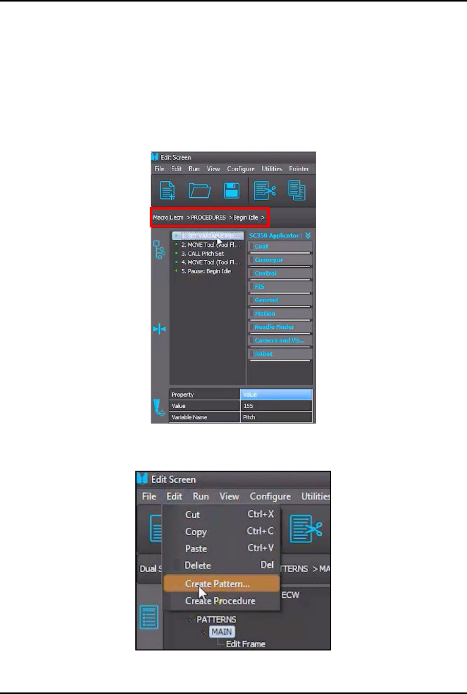
1. In the Edit Screen, load the Macro1.ecm > PROCEDURES > Begin Idle procedure
(Figure 4-56).
> The first two (2) instructions in the procedure are designed to match the pitch for both
valves to the pitch of the solvent cups.
Figure 4-56 Load Begin Idle Procedure
2. In the Edit Screen, select Edit > Create Pattern (Figure 4-57).
Figure 4-57 Select Create Pattern