SIPLACE X-Series (SIPLACE X-Series S, from SC 708.1) Edition 05/2015 EN User manual.pdf - 第129页
User manual SIPLACE X-Series 3 Technical data and assemblies From software version 708.1 Version 05/2015 3.5 Placement head 129 3.5.2 SIPLACE SpeedS tar C&P20 M for high -precision placement 3 Fig. 3.5 - 3 SIPLACE C&…
3 Technical data and assemblies User manual SIPLACE X-Series
3.5 Placement head From software version 708.1 Version 05/2015
128
3.5.1.2 Technical data SIPLACE SpeedStar (C&P20)
3
SIPLACE SpeedStar (C&P20)
with component camera
type 23
with component camera type 41
Component range
*a
*)a Please note that the placeable component range is also affected by the pad geometry, the customer-spe-
cific standards, the component packaging tolerances and the component tolerances.
01005 to 2220, Melf, SOT,
SOD
03015 mmto 2220, Melf, SOT,
SOD, Bare-Die, Flip-Chip
Component spec.
Max. height
Min. lead pitch
Min. lead width
Min. ball pitch
Min. ball diameter
Min. dimensions
Max. dimensions
Max. weight
4 mm
0.25 mm
0.1 mm
0.4 mm
0.2 mm
0.4 mm x 0.2 mm
6mm x 6 mm
1 g
4 mm
0.08 mm
0.03 mm
0.10 mm
0.05 mm
0.12 mm x 0.12 mm
6 mm x 6 mm
1 g
Programmable set-down
force
1.5 - 4.5 N 1.5 - 4.5 N
Nozzle types 10xx, 11xx, 12xx 10xx, 11xx, 12xx
X/Y accuracy
*b
*)b The SIPLACE benchmark value is measured during the machine acceptance tests. It corresponds to the
conditions set out in the SIPLACE scope of service and supply.
± 41 µm/3σ
± 55 µm/4σ
± 41 µm/3σ
± 55 µm/4σ
Angular accuracy ± 0.5° / 3σ
± 0.7° / 4σ
± 0.5° / 3σ
± 0.7° / 4σ
Illumination level 5 5
Possible illumination
level settings
256
5
256
5
User manual SIPLACE X-Series 3 Technical data and assemblies
From software version 708.1 Version 05/2015 3.5 Placement head
129
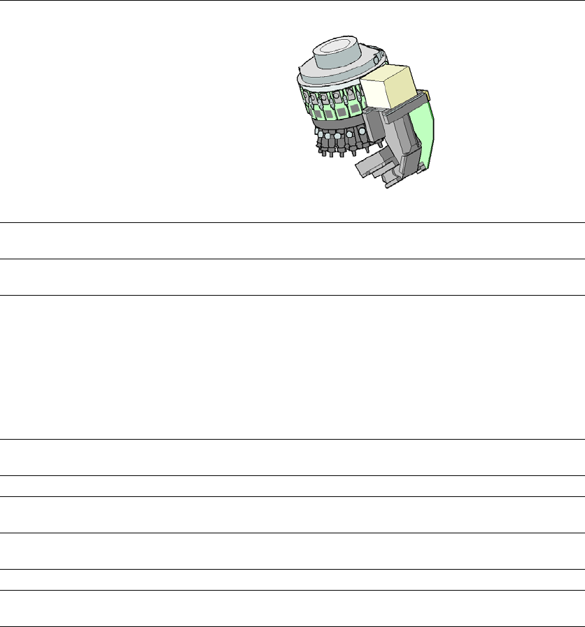
3.5.2 SIPLACE SpeedStar C&P20 M for high-precision placement
3
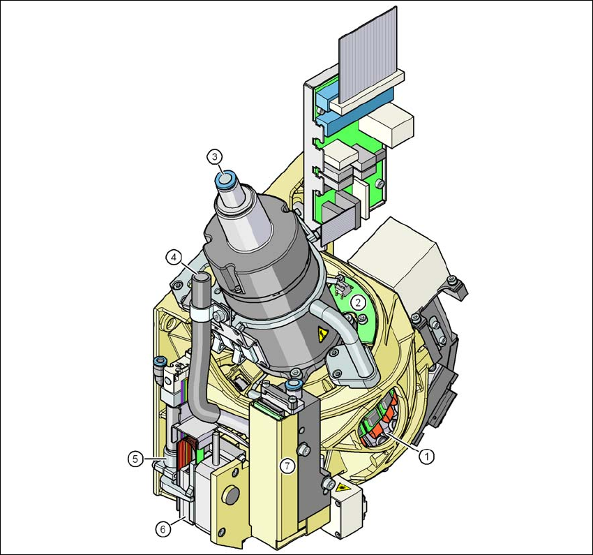
Fig. 3.5 - 3 SIPLACE C&P20 M - function group part 1
(1) DP drive, 20 drives
(2) "Vacuum sensor hold circuit" board
(3) Compressed air connection for 20 Venturi nozzles in the pickup/placement and holding circuit
(4) Line for the exhaust air from the pressure control valve (7)
(5) Return cylinder
(6) Z motor (linear motor)
(7) Pressure control valve
3 Technical data and assemblies User manual SIPLACE X-Series
3.5 Placement head From software version 708.1 Version 05/2015
130
3
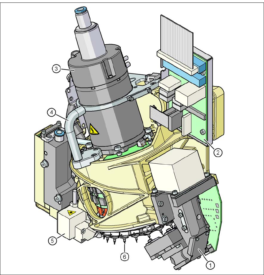
Fig. 3.5 - 4 SIPLACE C&P20 M - function group part 2
(1) C&P component camera, type 23, 6 x 6, digital
(2) Intermediate distributor board
(3) Star motor
(4) Handle
(5) Component sensor
(6) Star with 20 nozzles