SIPLACE X-Series (SIPLACE X-Series S, from SC 708.1) Edition 05/2015 EN User manual.pdf - 第250页
4 Setting up and commissioning User manual SIPLACE X-Series 4.3 Setting up the machine From software version 708.1 Version 05/2015 250 4.3.8 Integrating the machine into the line Observe the g eneral wa rnings in secti…
User manual SIPLACE X-Series 4 Setting up and commissioning
From software version 708.1 Version 05/2015 4.3 Setting up the machine
249
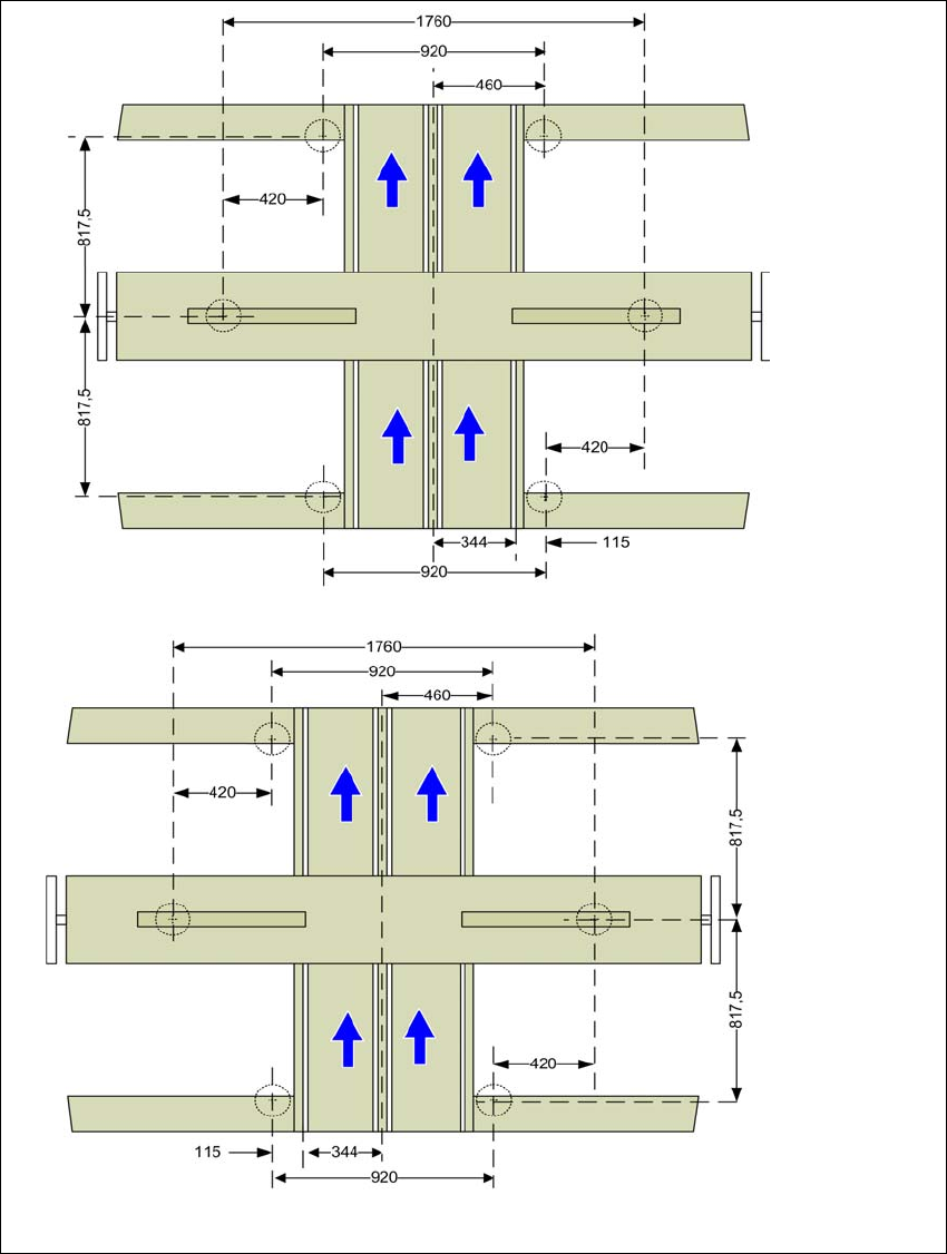
4.3.7.1 Machine foot clearances for the PCB dual conveyor
4
Fig. 4.3 - 9 Machine foot clearances for the PCB dual conveyor in millimeters
Fixed conveyor side at maxi-
mum right position
a
.
a) The value depends on the position of the fixed side. All dimensions in millimeters.
Fixed conveyor side at maxi-
mum left position
a
.
4 Setting up and commissioning User manual SIPLACE X-Series
4.3 Setting up the machine From software version 708.1 Version 05/2015
250
4.3.8 Integrating the machine into the line
Observe the general warnings in section 4.3.1, page 235.
Observe the warnings for transportation of the machine in section 4.3.2, page 236.
For details of tools and equipment, refer to section 4.3.5, page 239.
4.3.8.1 Aligning and adjusting the machines in the line
With the fork-lift, raise the machine until the weight is taken off the machine feet.
Determine the PCB conveyor height for the machine in the line and use the hexagon socket
head screw to adjust the height approximately.
You may need to fit the machine feet to the relevant PCB conveyor height (see 4.3.6 on page
240).
Position the machine on the free location on the line using the fork-lift.
Pay attention to the alignment of the PCB conveyors and check the distance to the previous
machine.
4
4
WARNING
Risk of damage!
If the machine feet on one side hit the ground hard, the fixings may be damaged.
Lower the machine slowly.
A second person should look underneath to ensure that all the machine foot touch
the floor at the same time.
User manual SIPLACE X-Series 4 Setting up and commissioning
From software version 708.1 Version 05/2015 4.3 Setting up the machine
251
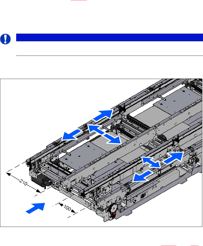
Align the machine in the X and Y direction with the help of the machine spirit level.
Place the machine spirit level in the X and then the Y direction on the sides of the conveyor
in placement area 1 (see fig. 4.3 - 10
). The board conveyor width has been preset:
Single conveyor 210 mm
Dual conveyor, lane 1 100 mm
Dual conveyor, lane 2 210 mm 4
4
Measure the distance between the upper edge of the PCB conveyor belt and the underside.
This distance should be 900 mm, 930 mm or 950 mm.
4
Fig. 4.3 - 10 Adjusting the machine in the X and Y directions
Use the fork wrench to adjust the setting screw M24x2x120 (item 1 in fig. 4.3 - 11, page 252),
so that the fluid in the machine spirit level does not deviate from its zero point at the required
conveyor height.
PLEASE NOTE
When using a dual conveyor, always place the spirit level on the outer sides of the
machine for measuring the X direction.