SIPLACE X-Series (SIPLACE X-Series S, from SC 708.1) Edition 05/2015 EN User manual.pdf - 第136页
3 Technical data and assemblies User manual SIPLACE X-Series 3.5 Placement head From software version 708.1 Version 05/2015 136 3.5.4 Sensor for the component reject bin The sensor for the component reject bin mo nitors …
User manual SIPLACE X-Series 3 Technical data and assemblies
From software version 708.1 Version 05/2015 3.5 Placement head
135
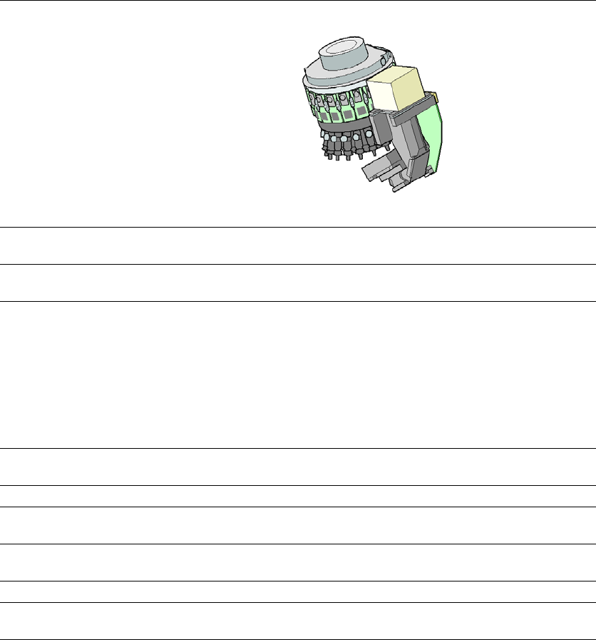
3.5.3.2 Technical data SIPLACE SpeedStar (C&P20 P)
3
SIPLACE SpeedStar (C&P20 P)
with component camera
type 23
with component camera type 41
Component range
*a
*)a Please note that the placeable component range is also affected by the pad geometry, the customer-spe-
cific standards, the component packaging tolerances and the component tolerances.
01005 to 2220, Melf, SOT,
SOD
03015 mmto 2220, Melf, SOT,
SOD, Bare-Die, Flip-Chip
Component spec.
Max. height
Min. lead pitch
Min. lead width
Min. ball pitch
Min. ball diameter
Min. dimensions
Max. dimensions
Max. weight
4 mm
0.25 mm
0.1 mm
0.4 mm
0.2 mm
0.4 mm x 0.2 mm
6 mm x 6 mm
1 g
4 mm
0.08 mm
0.03 mm
0.10 mm
0.05 mm
0.12 mm x 0.12 mm
6 mm x 6 mm
1 g
Programmable set-down
force
1.3 - 4.5 N 1.3 - 4.5 N
Nozzle types 40xx 40xx
X/Y accuracy
*b
*)b The SIPLACE benchmark value is measured during the machine acceptance tests. It corresponds to the
conditions set out in the SIPLACE scope of service and supply.
± 36 µm/3σ
± 48 µm/4σ
± 36 µm/3σ
± 48 µm/4σ
Angular accuracy ± 0.5° / 3σ
± 0.7° / 4σ
± 0.5° / 3σ
± 0.7° / 4σ
Illumination level 5 5
Possible illumination
level settings
256
5
256
5
3 Technical data and assemblies User manual SIPLACE X-Series
3.5 Placement head From software version 708.1 Version 05/2015
136
3.5.4 Sensor for the component reject bin
The sensor for the component reject bin monitors whether the reject bin is seated correctly in its
mount.
– If the reject bin was not inserted correctly, the machine cannot be started.
– If the reject bin jumps out of its mount during the placement process, the machine is stopped
immediately to avoid a head crash.
3.5.5 Vacuum pump
3.5.5.1 Overview
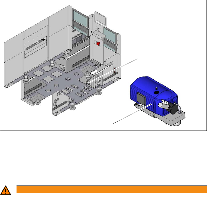
The vacuum pumps are fitted behind the COT inserts at location 1 and location 4 in the machine
base.
3
Fig. 3.5 - 6 Overview - vacuum pump
(1) Installation location for vacuum pump
(2) Vacuum pump
3.5.5.2 Safety instructions for vacuum pumps
3
(1)
(2)
WARNING
Please observe the safety instructions in the user manual supplied.

User manual SIPLACE X-Series 3 Technical data and assemblies
From software version 708.1 Version 05/2015 3.5 Placement head
137
3.5.5.3 Description
Each Collect&Place head has its own vacuum generator, which supplies the holding and place-
ment circuit with the required vacuum. The vacuum generator for the placement heads functions
according to the Venturi principle. When operated together with a vacuum pump, the compressed
air consumption for the SpeedStar (C&P20/M/P) head can be reduced considerably. A vacuum
pump can supply up to two SpeedStar (C&P20/M/P) heads. A maximum of two vacuum pumps
can therefore be used (for 4x C&P20/M/P). The running costs will fall according to the energy
costs incurred.
The vacuum pump is switched on and off with the machine. The station software automatically
takes into account an overrun time of 6 minutes, to prevent the motor overheating.
3
3.5.5.4 Maintenance instructions
Observe the additional maintenance instructions for the vacuum pump.
Read the relevant section in the maintenance manual for your machine.
PLEASE NOTE
The compressed air consumption values can be found in section 3.2.4
, page 118.