SIPLACE X-Series (SIPLACE X-Series S, from SC 708.1) Edition 05/2015 EN User manual.pdf - 第332页
6 Station extensions User manual SIPLACE X-Series 6.1 Nozzle changer From software version 708.1 Version 05/2015 332 6.1.2.8 Assembly The nozzle changer s are fixed to the COT insert. 6 Fig. 6.1 - 6 Assembly position (1)…
User manual SIPLACE X-Series 6 Station extensions
From software version 708.1 Version 05/2015 6.1 Nozzle changer
331
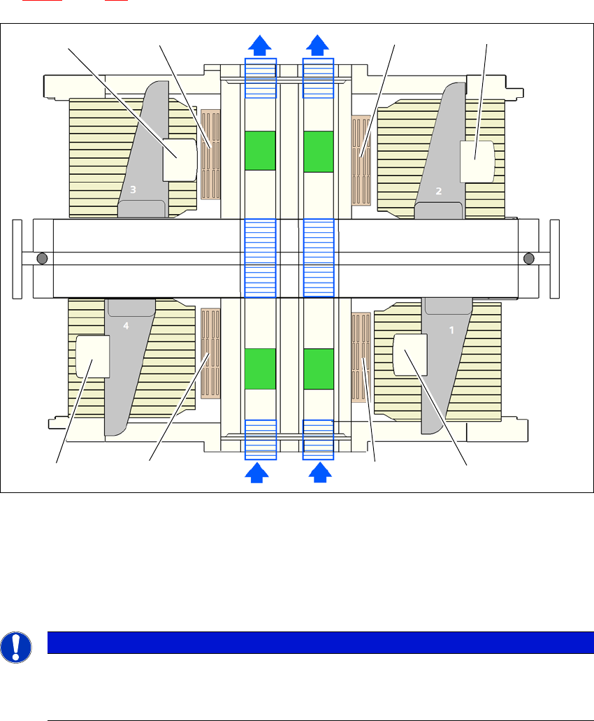
6.1.2.6 Configuration example: C&P20/C&P20 M for SIPLACE X4 S
Locations 1, 2, 3 and 4 can each accommodate one nozzle changer for the SpeedStar (item 1 in
fig. 6.1 - 5
, page 331).
6
Fig. 6.1 - 5 Position of nozzle changer for the SIPLACE SpeedStar machine - configuration example (SIPLACE X4
S)
6
6
6.1.2.7 Nozzle changer "row 2" for the SIPLACE SpeedStar
The "nozzle changer for row 2" option enables you to configure an additional row of nozzle chang-
ers for the SIPLACE SpeedStar. The retrofit package contains the nozzle changer and an assem-
bly kit.
(1) Nozzle changer
(2) SIPLACE SpeedStar
PLEASE NOTE
Stop machine if magazine missing
The safety circuit stops the machine if magazines are missing or not fitted correctly.
Use all magazine places.
(2)
(1)
(1)
(2)
(1)
(2) (2)
(1)
6 Station extensions User manual SIPLACE X-Series
6.1 Nozzle changer From software version 708.1 Version 05/2015
332
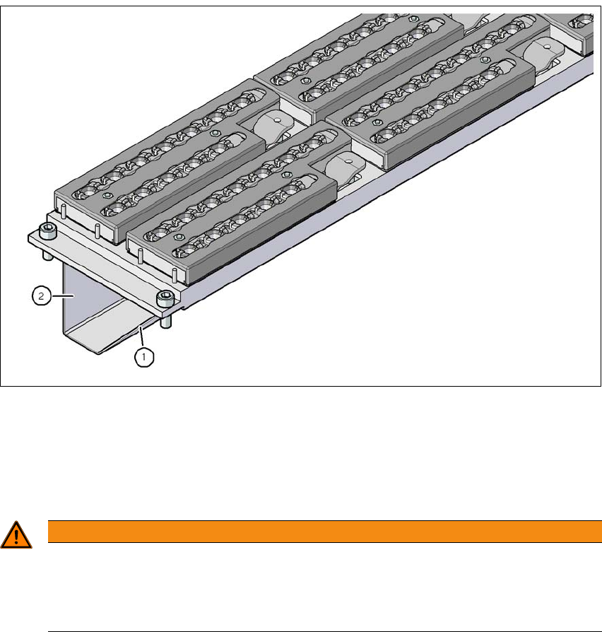
6.1.2.8 Assembly
The nozzle changers are fixed to the COT insert.
6
Fig. 6.1 - 6 Assembly position
(1) Sloping side points towards the COT insert
(2) Vertical side points towards the PCB conveyor
Align the nozzle changer so that the sloping side points towards the COT insert.
6
WARNING
Risk of head crashes with mixed configurations!
There is a risk of head crashes with mixed configurations.
Only install the associated nozzle changer for each placement head, with the nozzle
magazines for the respective placement head.
User manual SIPLACE X-Series 6 Station extensions
From software version 708.1 Version 05/2015 6.1 Nozzle changer
333
6.1.2.9 Notes on operation
When you fill a magazine with a certain nozzle type for the first time, attach an adhesive label
to identify the type.
6
Open the locking plate and place the nozzles in the nozzle holders.
Close the locking plate so that the nozzles cannot drop out of the magazines.
6
6
Programming the nozzle changer is described in the SIPLACE Pro user manual.
6.1.2.10 Changing the magazine
Press the lever (item 1 in fig. 6.1 - 7, page 334), to release the magazine from the balls of the
snap fasteners (item 5 in fig. 6.1 - 7
, page 334). Lift the magazine off the base.
6
PLEASE NOTE
Fill the magazines off the machine and always replace complete magazines.
CAUTION
Filling up magazines!
Before you fill magazines, make sure that all the nozzles on the Collect&Place head
have
been returned to their magazines.
PLEASE NOTE
Risk of jamming!
If components fall onto magazines, there is a risk that the locking plate could jam.
Do not allow components to drop onto the magazines.
You should therefore regularly clean the magazines and free locations.
WARNING
Risk of head crashes with protruding lever
Any lever that is protruding over the magazine (item 1 in fig 6.1 - 7
) can result in a head
crash.
You should therefore make sure that the lever does not protrude over the maga-
zines.