SIPLACE X-Series (SIPLACE X-Series S, from SC 708.1) Edition 05/2015 EN User manual.pdf - 第216页
3 Technical data and assemblies User manual SIPLACE X-Series 3.10 Component trolley From software version 708.1 Version 05/2015 216 3.10.10 Empty tape duct on the COT insert In the st andard version, the empty tape du ct…
User manual SIPLACE X-Series 3 Technical data and assemblies
From software version 708.1 Version 05/2015 3.10 Component trolley
215
3.10.8.2 Maximum tape reel diameter in relation to the PCB conveyor height
3
3
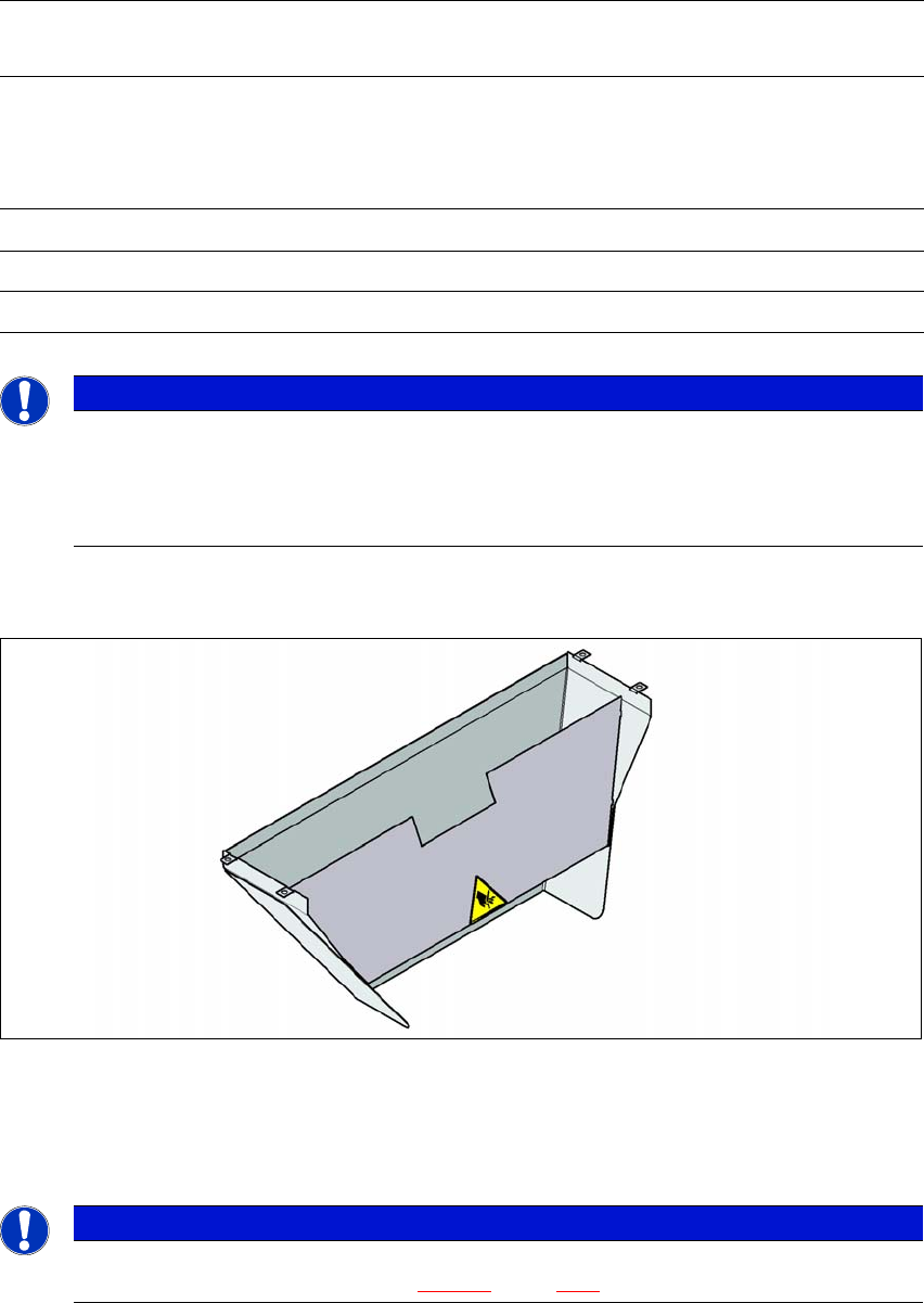
3.10.9 Used tape chute
3
Fig. 3.10 - 10 Used tape chute for the COT insert
In accordance with the PCB conveyor height, the length of the used tape chute can be set so that
the tape cuttings are directly diverted into the waste tape container of the component trolley.
3
Without mount for the
additional tape reel
With mount for the
additional tape reel
PCB conveyor
height
of the component
trolley
Tape reel diameter Tape reel diameter
without spindle with spindle
900 mm 19" 17" 15"
930 mm 19" 19" 17"
950 mm 19" 19" 19"
PLEASE NOTE
Using spindles
SIPLACE X-Series component trolleys do not generally need spindles.
Use spindles if the error message "Timeout" appears frequently on the X feeder
module.
PLEASE NOTE
The used tape chute for the SIPLACE X-Series can only be installed on the COT insert
for the SIPLACE X-Series (see fig. 5.15 - 3
, page 322).
3 Technical data and assemblies User manual SIPLACE X-Series
3.10 Component trolley From software version 708.1 Version 05/2015
216
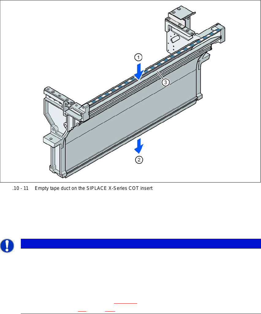
3.10.10 Empty tape duct on the COT insert
In the standard version, the empty tape duct can guide component tapes with a maximum pocket
height of 8 mm to the pneumatic tape cutter.
3
Fig. 3.10 - 11 Empty tape duct on the SIPLACE X-Series COT insert
(1) Inlet slot for used tape
(2) Outlet slot for the used tape above the pneumatic tape cutter
(3) Dividing plate for tapes < 8 mm (can be removed for tapes > 8 mm)
3
PLEASE NOTE
Risk of blockages!
When using feeder modules with low pockets next to feeder modules with high pockets,
there is a risk of blockages in the empty tapes.
Do not position feeder modules with shallow pockets immediately beside feeder
modules with deep pockets.
The separating plate (item 3 in fig. 3.10 - 11
) can be removed for tape pockets higher than
12 mm (see section 4.5
, page 258).
User manual SIPLACE X-Series 4 Setting up and commissioning
From software version 708.1 Version 05/2015 4.1 Transportation and delivery configuration
217
4 Setting up and commissioning
4.1 Transportation and delivery configuration
4.1.1 Shipping packaging
Within Europe, the machine and component trolleys will be shipped on two wooden pallets, pack-
aged in plastic film. Outside Europe, the machine and component trolleys are supplied in wooden
crates.
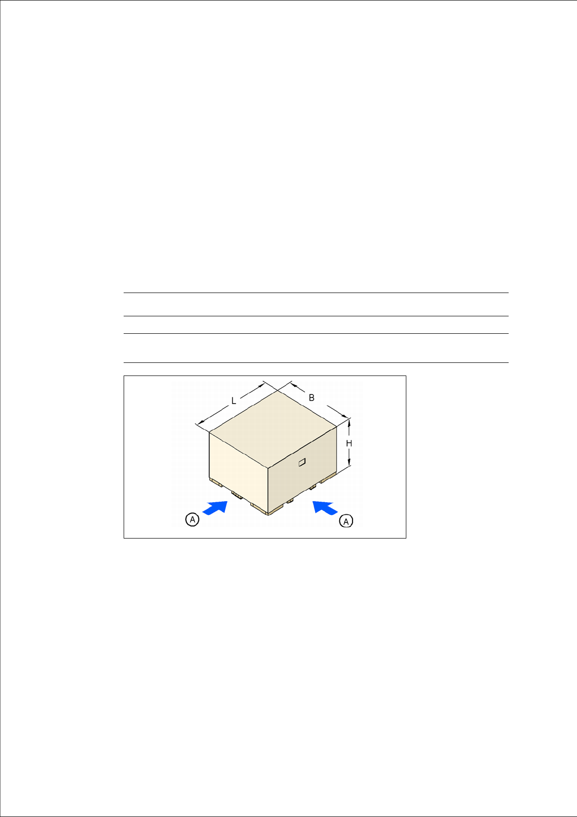
4.1.1.1 Shipping packaging dimensions
The dimensions of the pallets and wooden crates are listed in the following table:
4
Fig. 4.1 - 1 Transport crate - dimensions in millimeters
(A) Fork-lift attachment points
Machine (L x W x H) Component trolley
Pallet 2790 mm x 2404 mm 2060 mm x 1350 mm
Wooden
crate
2790 mm x 24040 mm x 1600 mm 2060 mm x 1350 mm x 1300 mm