SIPLACE X-Series (SIPLACE X-Series S, from SC 708.1) Edition 05/2015 EN User manual.pdf - 第91页
User manual SIPLACE X-Series 2 Operational safety From software version 708.1 Version 05/2015 2.6 Safety features 91 2.6.5 EMERGENCY STOP loop s and signalin g circuit 2.6.5.1 EMERGENCY STOP loop st ructure The following…
2 Operational safety User manual SIPLACE X-Series
2.6 Safety features From software version 708.1 Version 05/2015
90
Safety cutoff (CSB) (item 1 in fig. 2.6 - 8, page 89) 2
The safety cutoff (CSB) is located in the power supply unit. It is used to monitor the EMERGENCY
STOP circuits and safety equipment.
2
There are three conditions that must be fulfilled in order to activate the safety cutoff (CBS):
– The "software release" or "Control ON" signal must be issued.
– The EMERGENCY STOP loop must be closed.
– The start button must have been pressed.
Service socket (item 2 in fig. 2.6 - 8, page 89) 2
The service socket is contained in the power supply unit and is protected by the cover. It can only
be used if the machine is connected to the main power supply via a 5-wire connection (L1, L2, L3,
N, and PE). If a 4-wire connection is used, e.g. without N, the socket cannot be used.
2
DANGER
Lethal voltages under the safety cutoff (CSB) cover!
Under the cover there are components which could still carry lethal voltages, even when
the machine is switched off and the mains plug has been disconnected. After disconnect-
ing the mains plug, wait 5 minutes until the capacitors have discharged.
Never open the covers.
Only ASM Assembly Systems GmbH&Co.KG service engineers or the machine
owner's service engineers, who have been trained by ASM, may perform work on the
power supply and the safety cutoff (CBS).
WARNING
Safety instructions about lethal voltages!
Always follow the safety instructions concerning potentially lethal voltages - even
when the machine is switched off. (See section 2.1.3
from page 46 and section
2.6.3.3
from page 87 .
User manual SIPLACE X-Series 2 Operational safety
From software version 708.1 Version 05/2015 2.6 Safety features
91
2.6.5 EMERGENCY STOP loops and signaling circuit
2.6.5.1 EMERGENCY STOP loop structure
The following contacts are connected in series and form the EMERGENCY STOP loop:
– Make contact elements for the four protective cover switches
– Make contact elements for service flaps (up to 4 service flaps available as an option)
– Normally open (NO) contacts for the two EMERGENCY STOP buttons
– Make contact elements for the four component trolleys
2.6.5.2 Signaling circuit structure
The following modules in the signaling circuit are queried individually:
– The protective cover switches
– Protective switches for service flaps (up to 4 service flaps available as an option)
– Signaling contacts on the component trolley
– EMERGENCY STOP button
All the signaling contacts are closed when the machine is on standby. If a protective cover, for ex-
ample, is raised, the associated signaling contact opens. This status change is signaled to the
control computer via a digital CAN bus input signal from the I/O control unit. An error message to
this effect appears on the user interface.
2.6.5.3 Description of the functions of the EMERGENCY STOP loops
The following conditions must be fulfilled in order to start and operate the machine:
– All component trolleys must be docked in and connected.
– All protective covers must be closed.
– All service flaps must be closed (up to 4 service flaps available as an option).
– Both emergency stop buttons must be released.
– The minimum operating pressure must have been reached.
– The software release ("Control ON") must be enabled, so that the start signal from the "Start"
button can switch on the safety cutoff (CBS).
If one of the start buttons is now pressed, the safety cutoff (CBS) will switch and the machine will
be ready for operation.
2 Operational safety User manual SIPLACE X-Series
2.6 Safety features From software version 708.1 Version 05/2015
92
2
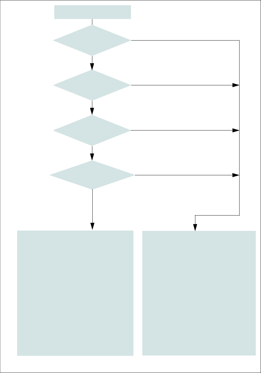
Fig. 2.6 - 9 EMERGENCY STOP loops
Start button pressed.
No
No
Yes
No
No
Yes
Yes
2
Active
Safety cutoff No
Voltage
Y axis 0 V
X axis 0 V
Star axis 0 V
DP axis 42 V-
Z axis (C&P, TH) 42 V-
Z axis (CPP) 0 V-
Active
PCB conveyor No
Lifting table No
PCB clamping No
Width adjustment No
Tape cutter No
Component trolley feeding device Yes
Yes
Compressed
air min. 0.5 MPa
(5.0 bar)?
EMERGENCY STOP button
pressed?
- Protective cover and/or
service flap open?
Component trolley
EMERGENCY STOP circuit
interrupted?
0
Active
Safety cutoff Yes
Voltage
Y axis 300 V-
X axis 300 V-
Star axis 160 V-
DP axis 42 V-
Z axis (C&P, TH) 42 V-
Z axis (CPP) 160 V-
Active
PCB conveyor Yes
Lifting table Yes
PCB clamping Yes
Width adjustment Yes
Tape cutter. Yes
Component trolley feeding device Yes