SIPLACE X-Series (SIPLACE X-Series S, from SC 708.1) Edition 05/2015 EN User manual.pdf - 第231页
User manual SIPLACE X-Series 4 Setting up and commissioning From software version 708.1 Version 05/2015 4.2 Infrastructure at the installation location 231 4.2.3.4 Mains connection - delivery configuration The main power…

4 Setting up and commissioning User manual SIPLACE X-Series
4.2 Infrastructure at the installation location From software version 708.1 Version 05/2015
230
4.2.3.3 Power supply cable - specification
The following specifications apply to the power supply cable for the machine:
– 5 x 4 mm² for 3 x 360 V~ to 3 x 480 V ± 10 %, 50/60 Hz mains voltage for a cable length of
up to 10 meters to the machine mains power cable.
Over 10 meters cable 5 x 6 mm².
– 5 x 4 mm² for 3 x 200 V~ to 3 x 240 V~ ± 10 %; 50/60 Hz mains voltage for a cable length of
up to 10 meters to the machine mains power cable.
Over 10 meters cable 5 x 6 mm².
The color coding for the wires will depend on the country in which the system is operated.
4
WARNING
Clear marking of electrical leads!
The electrical leads to each individual machine and to the options installed must be clear-
ly labeled and easily assignable.
The regulations of the country in which the machine is operated apply.
User manual SIPLACE X-Series 4 Setting up and commissioning
From software version 708.1 Version 05/2015 4.2 Infrastructure at the installation location
231
4.2.3.4 Mains connection - delivery configuration
The main power connection is configured according to the power supply of the country concerned.
– The machine is configured for voltages of 3 x 200 V~ to 3 x 240 V~ ± 10 %; 50/60 Hz.
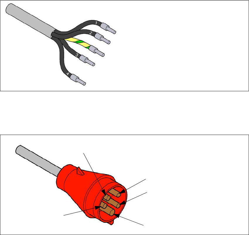
The machine has a mains power cable WITHOUT plug. 4
4
Fig. 4.2 - 4 Description of wires in the mains power cable
– The machine is configured for voltages of 3 x 360 V~ to 3 x 480 V ± 10 %, 50/60 Hz.
The machine has a mains power cable WITH Cekon plug. 4
4
Fig. 4.2 - 5 Assignment in the Cekon plug
1 = (L1): three-phase
2 = (L2): three-phase
3 = (L3): three-phase
4 = (N): neutral conductor
green/yellow = (PE): conductor
PE
L1
L2
L3
N
4 Setting up and commissioning User manual SIPLACE X-Series
4.2 Infrastructure at the installation location From software version 708.1 Version 05/2015
232
4.2.3.5 Connecting the power supply cable
4
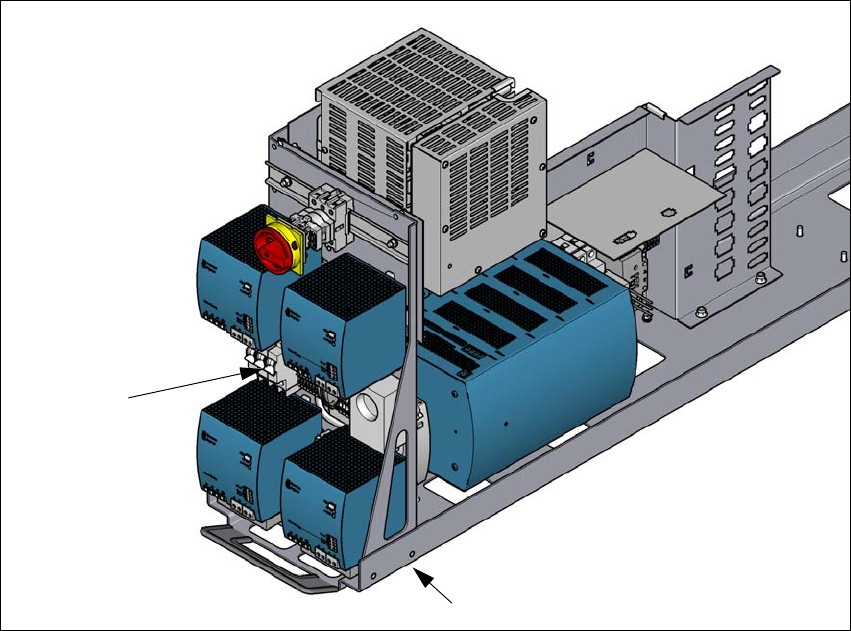
Fig. 4.2 - 6 Terminal panel for connecting the power cable
(1) Mains terminals (X95) for the power supply cable
(2) Opening on the power supply with cable fixture under the power supply
Crimp a ferrule onto each end of the wire.
Run the mains power cable through the cable fixture under the power supply (2) to the termi-
nal panel X95 (1).
Fasten the cable to the terminal panel X95 (1)
(L1): three-phase 4
(L2): three-phase 4
(L3): three-phase 4
(N): neutral conductor 4
(PE): PE conductor 4
Make sure that the bending radius is adequate. The wires must not be kinked.
Manually tighten the cable fixture.
Make sure you also fix the cable with cable ties.
(1)
(2)