CMV12000_DS000603_6-00.pdf - 第28页
Document Feedback CMV12000 Functional Description Datasheet • PUBLIC DS000603 • v6 - 00 • 2023 -Sep- 22 84 │ 27 Figure 21 : Internal Exposure Delay 2 When keeping the Frame_REQ pin continuously high, the sensor will cont…
Document Feedback
CMV12000
Functional Description
Datasheet • PUBLIC
DS000603 • v6-00 • 2023-Sep-22
84 │ 26
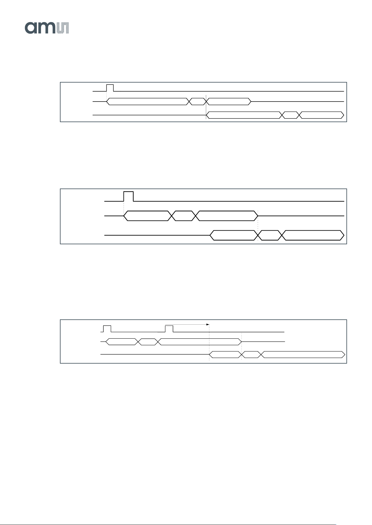
Figure 18:
Internal Exposure Request for Two Frames
When the exposure time is shorter than the read-out time, the FOT and read-out of the next frame will
start immediately after the read-out of the previous frame.
Figure 19:
Internal Exposure Request for Two Frames with Short Exposure Time
When you request a second frame during the read-out of the current frame, the current read-out will
always be finished before the FOT of the new requested frame starts. When the new Frame_REQ
pulse is too early, it will be delayed internally so that the FOT starts immediately after the readout.
Figure 20:
Internal Exposure Delay
If a second frame request is given during the integration of the current frame, the sensor will
remember this and delay the request as described above. This only works up to two Frame_REQ
pulses during integration.
FRAME_REQ
Exposure time
Frame1_cycle
FOT Read-out time
Exposure time
Frame2_cycle
FOT Read-out time
FRAME_REQ
Frame1_cycle
FOT Read-out time
Exposure time
Frame2_cycle
FOT Read-out time
Exposure time
FOT
READOUT
INTE
FOT READOUT
Frame_REQ
INTE
delayed
Current Frame
Next Frame
Document Feedback
CMV12000
Functional Description
Datasheet • PUBLIC
DS000603 • v6-00 • 2023-Sep-22
84 │ 27
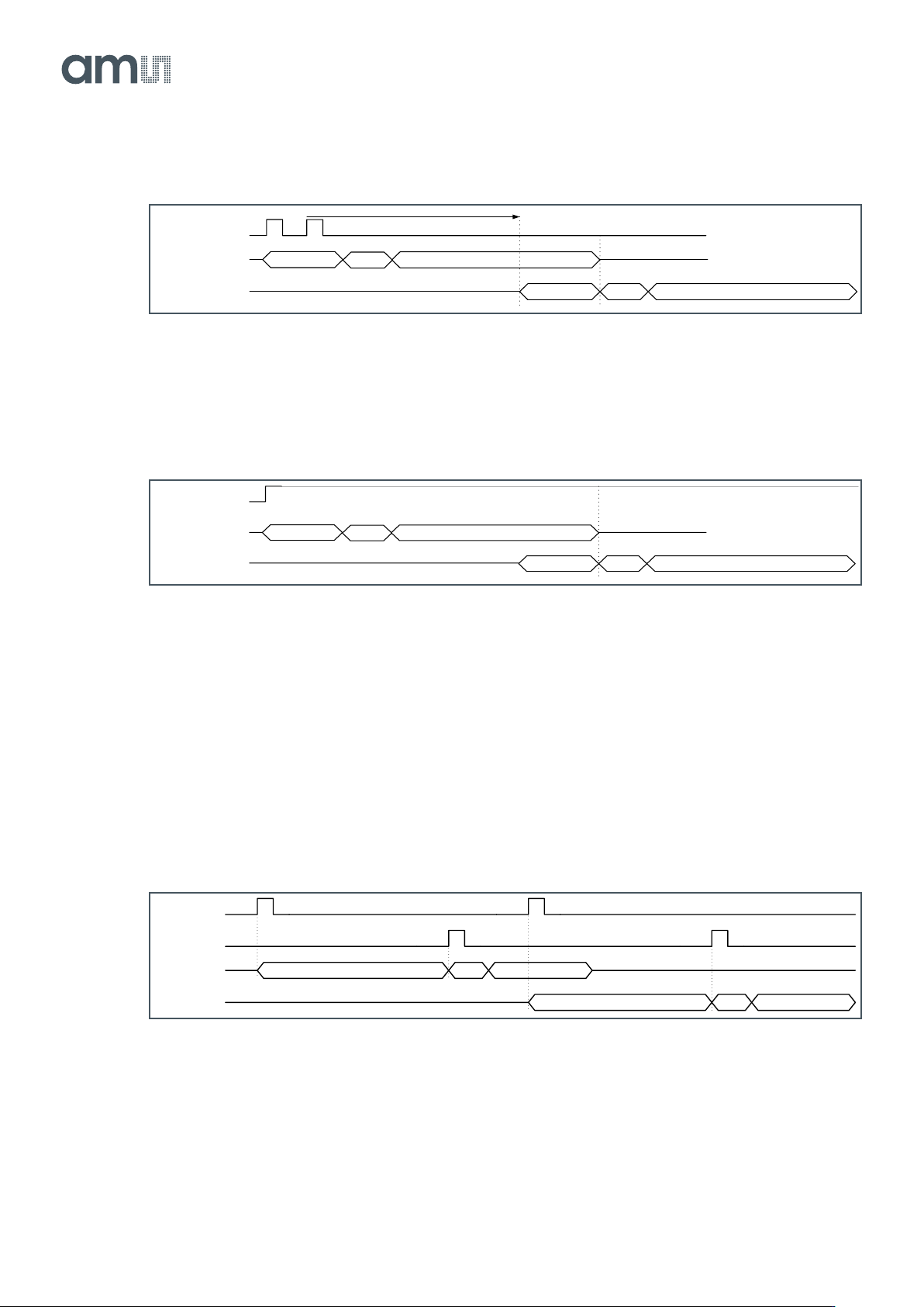
Figure 21:
Internal Exposure Delay 2
When keeping the Frame_REQ pin continuously high, the sensor will continuously read out frames at
the maximum achievable frame rate.
Figure 22:
Internal Continuous Exposure
External Exposure Control
The exposure time can also be programmed externally by using the T_EXP1 (and T_EXP2) input pin.
This mode needs to be enabled by setting the appropriate register (address 70[0]). In this case, the
exposure starts when a high state is detected on the T_EXP1 pin. When a high value is detected on
the FRAME_REQ input, the exposure time stops and the read-out will start automatically. A new
exposure can start by sending a pulse to the T_EXP1 pin during or after the read-out of the previous
frame.
Figure 23:
External Exposure Request for Two Frames
When the exposures stops too soon (by giving a Frame_REQ pulse during read-out), the current read-
out will be finished normally and the exposure time will be extended so that the FOT starts
immediately after the read-out.
FOT
READOUT
INTE
FOT READOUT
Frame_REQ
INTE
delayed
Current Frame
Next Frame
FOT
READOUT
INTE
FOT READOUT
Frame_REQ
INTE
Current Frame
Next Frame
FRAME_REQ
Exposure time
Frame1_cycle
FOT Read-out time
Exposure time
Frame2_cycle
FOT Read-out time
T_EXP1

Document Feedback
CMV12000
Functional Description
Datasheet • PUBLIC
DS000603 • v6-00 • 2023-Sep-22
84 │ 28
Figure 24:
External Exposure Extension
7.3 Sensor Readout Format
7.3.1 LVDS Outputs
The CMV12000 has LVDS (low voltage differential signaling) outputs to transport the image data to
the surrounding system. Next to 64 data channels, the sensor also has two other LVDS channels for
control and synchronization of the image data. In total, the sensor has 66 LVDS output pairs (2 pins
for each LVDS channel):
● 64 data channels
● 1 control channel
● 1 clock channel
This means that a total of 132 pins of the CMV12000 are used for the LVDS outputs (128 for data + 2
for LVDS clock + 2 for control channel). See the pin list in Figure 4 for the exact pin numbers of the
LVDS outputs.
The 64 data channels are used to transfer the 12-bit, 10-bit or 8-bit pixel data from the sensor to the
receiver in the surrounding system. The 32 bottom channels use pins OUT1_N/P to OUT32_N/P and
the top channels use pins OUT33_P/N to OUT64_P/N.
The output clock channel transports a clock, synchronous to the data on the other LVDS channels.
This clock can be used at the receiving end to sample the data. This clock is DDR, which means that
the frequency will be half of the output data rate. When 600 Mbit/s output data rate is used, the LVDS
output clock will be 300 MHz (half of input clock).
The data on the control channel contains status information on the validity of the data on the data
channels. Information on the control channel is grouped in 8-bit, 10-bit or 12-bit words that are
transferred synchronous to the 64 data channels.
FOT
READOUT
INTE
FOT READOUT
T_EXP
Frame_REQ
extended INTEINTE
delayed
Current Frame
Next Frame