CMV12000_DS000603_6-00.pdf - 第42页
Document Feedback CMV12000 Functional Description Datasheet • PUBLIC DS000603 • v6 - 00 • 2023 -Sep- 22 84 │ 41 When a color sensor is used, the sequencer should be programmed to make sure it t akes the bayer pattern int…
Document Feedback
CMV12000
Functional Description
Datasheet • PUBLIC
DS000603 • v6-00 • 2023-Sep-22
84 │ 40
Interleaved HDR
In this HDR mode, the odd and even columns of the image sensor will have a different exposure time.
This mode can be enabled by setting the register in the table below.
Figure 44:
Interleaved HDR Settings
Reg. Name
Address
Bits
Default
Description
Exp_dual
70
[1]
0
0: HDR Off
1: HDR On
The surrounding system can combine the image of the odd columns with the image of the even
columns, which can result in a high dynamic range image. In such an image, very bright and very dark
objects are made visible without clipping. The table below gives an overview of the registers involved
in the interleaved read-out when the internal exposure mode is selected.
Figure 45:
Interleaved HDR Exposure Settings
Reg. Name
Address
Bits
Default
Description
Exp_time
71
72
[15:0]
[7:0]
1536
Sets the exposure time for the even columns.
Exp_time2
73
74
[15:0]
[7:0]
1536
Sets the exposure time for the odd columns.
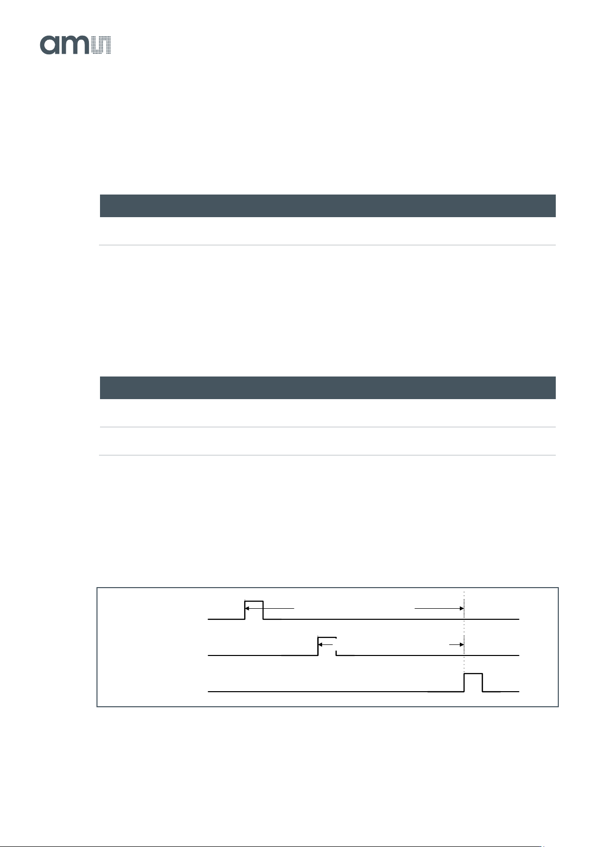
When the external exposure mode and interleaved read-out are selected, the different exposure times
are achieved by using the T_EXP1 and T_EXP2 input pins. T_EXP1 defines the exposure time for the
even columns, while T_EXP2 defines the exposure time for the odd columns. See the figure below for
more details.
Figure 46:
Interleaved HDR with External Exposure
FRAME_REQ
T_EXP1
T_EXP2
Exposure time even columns
Exposure time odd columns
Document Feedback
CMV12000
Functional Description
Datasheet • PUBLIC
DS000603 • v6-00 • 2023-Sep-22
84 │ 41
When a color sensor is used, the sequencer should be programmed to make sure it takes the bayer
pattern into account when doing interleaved read-out. This can be done by setting the appropriate
registers to ‘0’.
Figure 47:
Interleaved HDR Color Mode
Reg. Name
Address
Bits
Default
Description
Color
68
[0]
1
0: Color sensor
1: Monochrome sensor
Color_exp
68
[3]
1
0: Color sensor
1: Monochrome sensor
Multiple Slope HDR
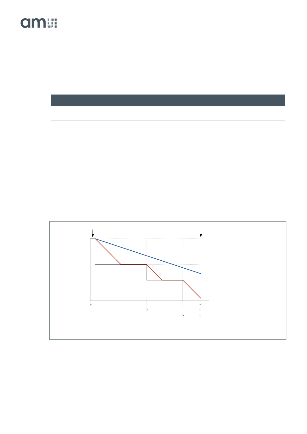
The CMV12000 has the possibility to achieve a high optical dynamic range by using a multiple slope
feature. This feature will partially reset those pixels, which reach a programmable voltage, while
leaving the other pixels untouched. This can be done 2 times within one exposure time to achieve a
maximum of three exposure slopes. See figure below for more details.
Figure 48:
Multiple Slope HDR
In the figure above, the red lines represent a pixel on which a large amount of light is falling. The blue
line represents a pixel on which less light is falling. As shown in the figure, the bright pixel is held to a
programmable voltage for a programmable time during the exposure time. This happens two times to
make sure that at the end of the exposure time, the pixel is not saturated. The darker pixel is not
Vhigh
Vtfl2
Vtfl3
Vlow
Total exposure time
Exp_kp2
Exp_kp1
Pixel reset Pixel sample
Document Feedback
CMV12000
Functional Description
Datasheet • PUBLIC
DS000603 • v6-00 • 2023-Sep-22
84 │ 42
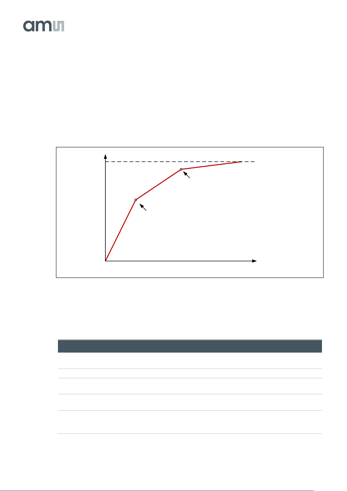
influenced by this multiple slope and will have a normal response. The Vtfl voltages and different
exposure times are programmable using the sequencer registers. Using this feature, a response as
detailed in the figure below can be achieved. The placement of the kneepoints in X is controlled by the
Vtfl programming (64 = Vlow; 127 = Vhigh), while the slope of the segments is controlled by the
programmed exposure times.
A good starting point is to set Exp_kp1 to 1% of the total exposure time and Exp_kp2 to 10% and
setting Vtfl2 to 84 and Vtfl3 to 104.
Figure 49:
Multiple Slope HDR Kneepoints
The following registers need to be programmed when multiple slopes in internal exposure mode are
desired.
Figure 50:
Multiple Slope HDR Settings with Internal Exposure
Reg. Name
Address
Bits
Default
Description
Exp_time
71
72
[15:0]
[7:0]
1536
Sets the total exposure time
Number_slopes
79
[1:0]
1
Sets the number of slopes (min=1, max=3)
Exp_kp1
75
76
[15:0]
[7:0]
0
Sets the exposure time of kneepoint 1
Exp_kp2
77
78
[15:0]
[7:0]
0
Sets the exposure time of kneepoint 2
Vtfl2
106
106[6:0]
64
Sets the level of kneepoint 1:
Bit [6] = 0/1: Enable/Disable DAC
Bits [5:0]: Vtfl2 voltage level
Saturation
level
Kneepoint 1
Kneepoint 2
# of electrons
Output signal