CMV12000_DS000603_6-00.pdf - 第38页
Document Feedback CMV12000 Functional Description Datasheet • PUBLIC DS000603 • v6 - 00 • 2023 -Sep- 22 84 │ 37 Reg. Name Address Bits Default Description Exp_time 71 72 [15:0] [7:0] 1536 Sets the exposure time in Intern…
Document Feedback
CMV12000
Functional Description
Datasheet • PUBLIC
DS000603 • v6-00 • 2023-Sep-22
84 │ 36
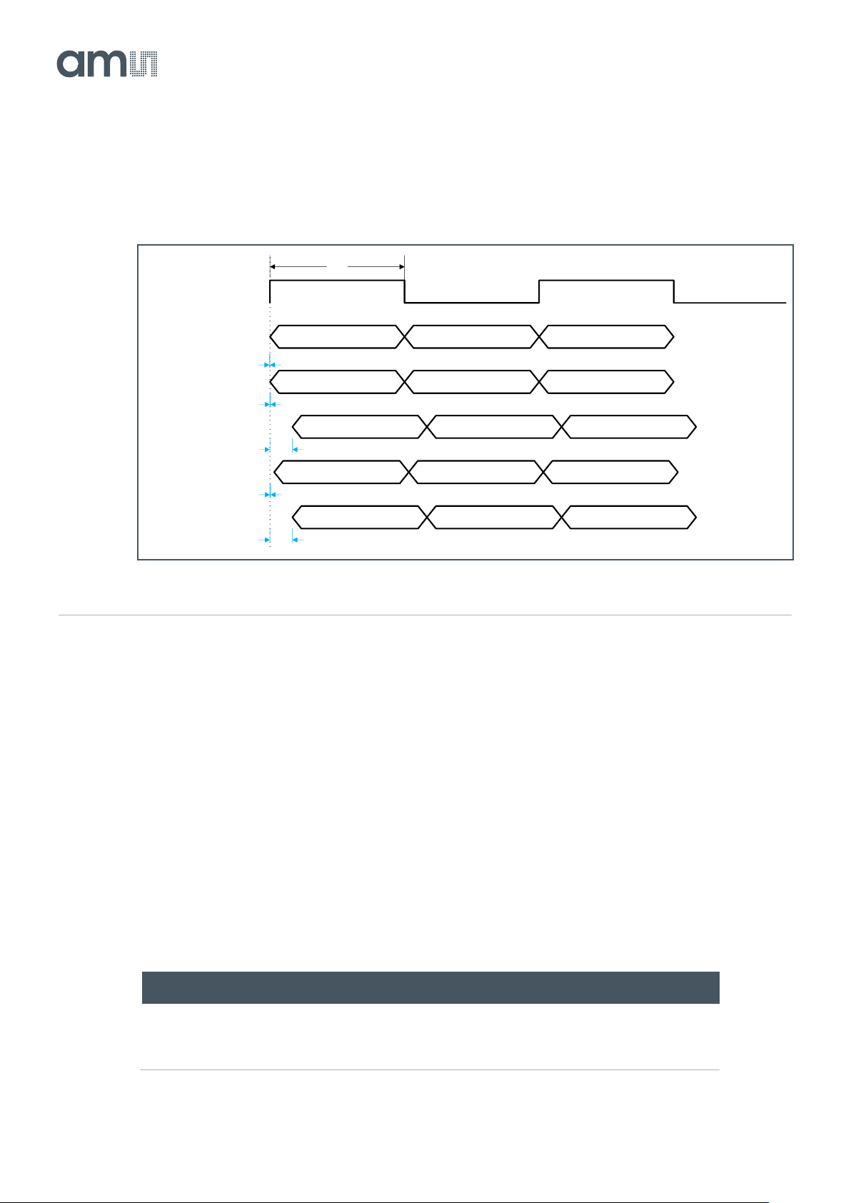
when (large) temperature changes occur. The skew can differ between devices; 150 ps is a typical
value.
Figure 38:
Typical LVDS Output Skew
7.4 Configuring Exposure and Readout
This section explains how the CMV12000 can be programmed using the on-board sequencer
registers.
7.4.1 Exposure Modes
The exposure time can be programmed in two ways, externally or internally. Externally, the exposure
time is defined as the time between the rising edge of T_EXP1 and the rising edge of FRAME_REQ
(see section 7.2.8 for more details). Internally, the exposure time is set by uploading the desired value
to the corresponding sequencer register.
The table below gives an overview of the registers involved in the exposure mode.
Figure 39:
Exposure Modes
Reg. Name
Address
Bits
Default
Description
Exp_ext
70
[7:0]
0
0: Internal Exposure Mode. Exposure time is defined by
register 71-72.
1: External Exposure Mode. Exposure time is defined
by T_EXPx and FRAME_REQ triggers.
T1
LVDS
CLOCK_OUT
CTR
CH1
CH2
CH33
CH34
D(0) D(1) D2)
D(0) D(1) D2)
D(0) D(1) D2)
D(0) D(1) D2)
D(0) D(1) D2)
+150ps
0 ps
0 ps
0 ps
+150ps
Document Feedback
CMV12000
Functional Description
Datasheet • PUBLIC
DS000603 • v6-00 • 2023-Sep-22
84 │ 37
Reg. Name
Address
Bits
Default
Description
Exp_time
71
72
[15:0]
[7:0]
1536
Sets the exposure time in Internal Exposure Mode
using the formula below.
The formula to calculate the actual exposure time in internal exposure mode from the programmed
registers is given by:
Equation 1:
The minimal exposure times when running at 600 MHz in internal mode will therefore be:
Figure 40:
Minimum Exposure Times in Internal Exposure Mode
When using external exposure mode, the actual exposure time will be given by:
Equation 2:
The time between the T_EXP and FRAME_REQ pulses will be clocked to a multiple of
(LVDS_CLK_P/N_period * #bits).
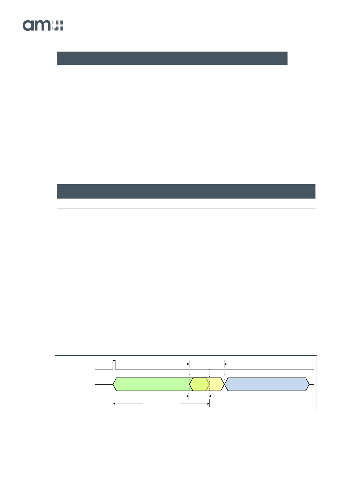
For both modes there is an overlap of the exposure during the FOT (= the (34 * reg82[7:0]) part).
Figure 41:
Exposure FOT Overlap
Bit Mode
Min. Exposure Time [µs]
8
15.4
10
15.3
12
20.4
Frame_REQ
Frame_cycle
Exposure time FOT
Actual exposure time
(reg82[15:8] + 2) * (reg85 + 1) * clk_per
Read-out time
(34 * reg82[7:0]) * clk_per

Document Feedback
CMV12000
Functional Description
Datasheet • PUBLIC
DS000603 • v6-00 • 2023-Sep-22
84 │ 38
7.4.2 Frame Timing
The frame rate of the CMV12000 is defined by two main factors.
● Exposure time
● Read-out time
FOT (Frame Overhead Time) will only have an influence when very few rows are read out.
For ease of use we will assume that the exposure time is equal to or shorter than the read-out time. By
assuming the frame rate is completely defined by the read-out time (because the exposure time
happens in parallel with the read-out time). The read-out time (and thus the frame rate) is defined by:
● Clock speed: 600 MHz maximum
● ADC mode: 8, 10 or 12-bit
● Number of lines read-out (windowing, subsampling or binning)
● Number of LVDS data outputs used: 64 maximum
This means that if any of the parameters above are changed, it will have an impact on the frame rate
of the sensor.
All timings can be expressed in line times:
Equation 3:
The total read-out time is composed of the FOT and the image readout time. The image readout time
is dependent of the total number of read out lines (#readout lines), sides used and the line time.
Equation 4:
Equation 5:
The number of lines read out will depend on the mode:
● Normal mode: #readout lines = Number_lines_tot
● X&Y-Subsampling: #readout lines = Number_lines_tot/2
● Binning: #readout lines = Number_lines_tot/4
Number_lines_tot is the value of register 1.
When running at 600 MHz in 10-bit mode with 64 output channels, register 82[15:8] is 12 and register
85 is 128. This will result in a line time of 2.15 µs, FOT of 30.1 µs and an image read-out time of
3.3024 ms for the full pixel array.