CMV12000_DS000603_6-00.pdf - 第71页
Document Feedback CMV12000 Functional Description Datasheet • PUBLIC DS000603 • v6 - 00 • 2023 -Sep- 22 84 │ 70 Figure 95 : ADC Range Multiplicatio n ADC_range_mult2 ADC_range_mult 0 ADC_range_mult 1 ADC_range_mult 3 0 ×…
Document Feedback
CMV12000
Functional Description
Datasheet • PUBLIC
DS000603 • v6-00 • 2023-Sep-22
84 │ 69
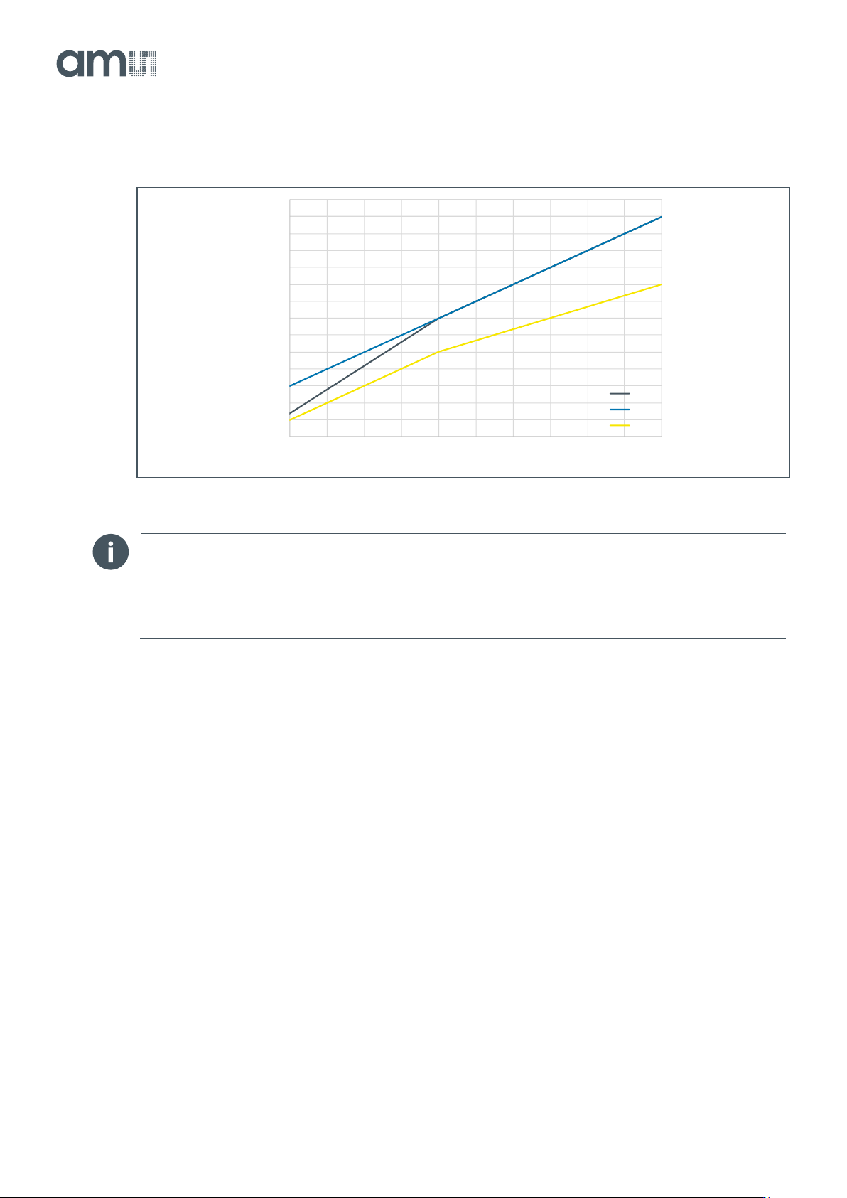
Figure 94:
FOT Register vs Clock Speed
Information
Bits [6:0] of register 107 do not change with clock speed. Keep these bits always the same, at the
recommended value from previous sections. For example at 10b default mode, register 107 =
11614, so bits [6:0] should remain 94.
ADC Range
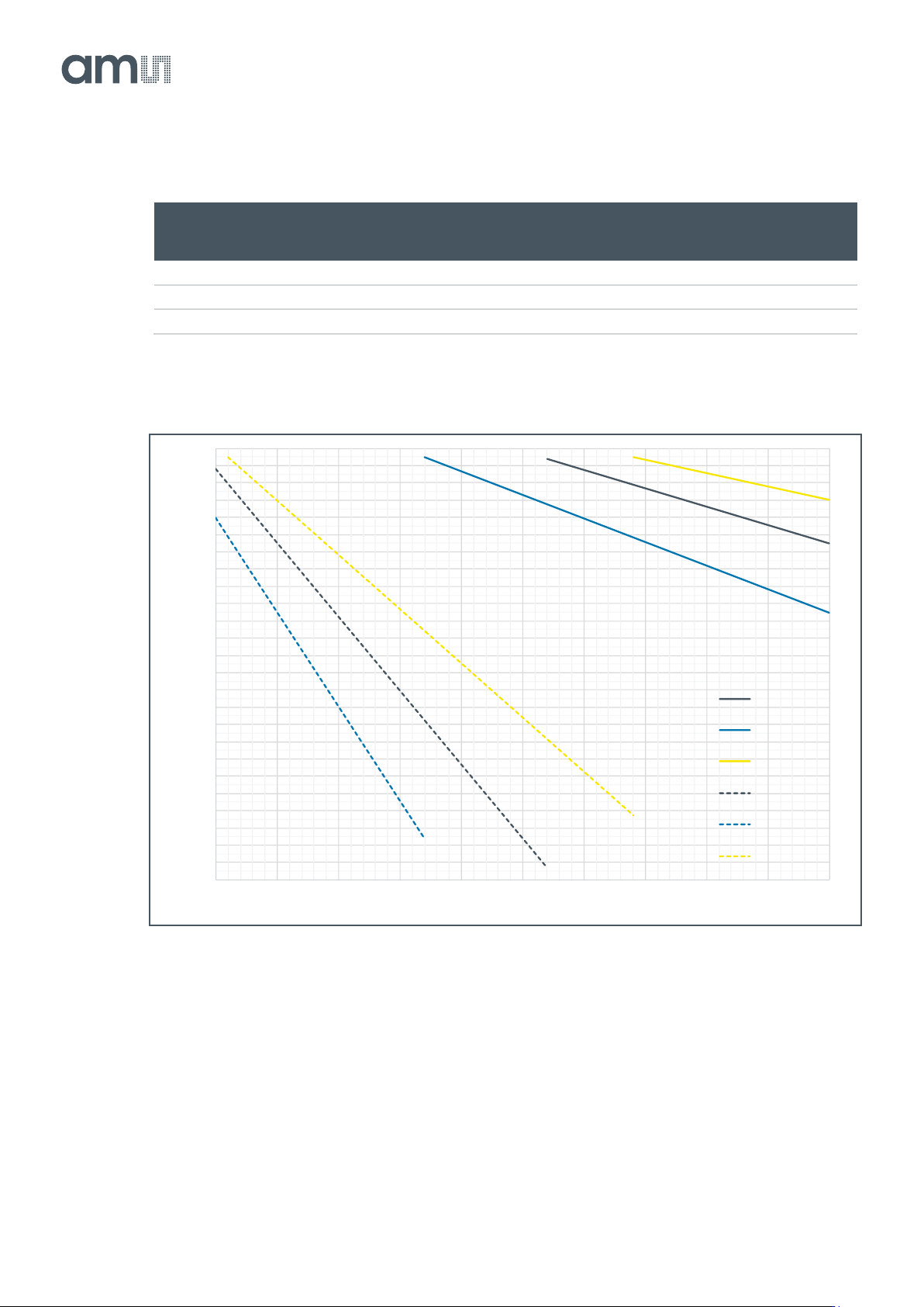
The ADC range is dependent of the input clock speed, the slower the clock the higher the ADC range
setting has to be. Below you can see a plot showing which ADC range and multipliers to use with a
certain clock speed and bit mode.
The multiplier registers set the total multiplication for the ADC input range. The table below gives an
overview of the total multiplication (used in Figure 96) that is applicable.
For example, when running at 400 MHz, make a vertical line on this frequency until crossing all 3
diagonal lines. Crossing the dashed yellow line, this refers to 12b_mult_x16. Then, find x16 on the
table from Figure 95, finally, you should use the values:
● ADC_range = 70, ADC_range_mult = 3, ADC_range_mult2 = 3 for 12b ADC.
● ADC_range = 220, ADC_range_mult = 1, ADC_range_mult2 = 0 for 10b ADC.
● ADC_range = 247, ADC_range_mult = 0, ADC_range_mult2 = 0 for 8b ADC.
77
78
79
80
81
82
83
84
85
86
87
88
89
90
91
100 150 200 250 300 350 400 450 500 550 600
Reg107[13:7]
LVDS Input CLK [MHz]
FOT register vs CLK
8b
10b
12b
Document Feedback
CMV12000
Functional Description
Datasheet • PUBLIC
DS000603 • v6-00 • 2023-Sep-22
84 │ 70
Figure 95:
ADC Range Multiplication
ADC_range_mult2
ADC_range_mult
0
ADC_range_mult
1
ADC_range_mult
3
0
×1
×2
×4
1
N/A
N/A
×8
3
N/A
N/A
×16
Figure 96:
ADC Range Settings
10
20
30
40
50
60
70
80
90
100
110
120
130
140
150
160
170
180
190
200
210
220
230
240
250
260
100 150 200 250 300 350 400 450 500 550 600
ADC_Range Setting [ ]
LVDS Input CLK [MHz]
8b_mult_x1
10b_mult_x2
12b_mult_x4
8b_mult_x4
10b_mult_x8
12b_mult_x16
Document Feedback
CMV12000
Register Description
Datasheet • PUBLIC
DS000603 • v6-00 • 2023-Sep-22
84 │ 71
8 Register Description
8.1 Register Categories
The registers are grouped into various categories, based on when they may (or not may) be updated
and synced. The table below explains the details of the various categories.
Figure 97:
Register Categories
Category
Description
-
Register without category that can be uploaded at any time, but might directly influence the
sensor execution.
SYNC
Registers are internally synchronized to the end of FOT, so the read out will be done with these
registers applied.
Registers can only be uploaded during IDLE or FOT.
FRAME
Registers will be internally synced at FRAME_REQ.
Registers can only be uploaded during IDLE.
INTE
Registers will be internally synced at start of INTE.
Registers can only be uploaded during IDLE or FOT.
DC
Registers will be internally synced immediately.
Registers can only be uploaded during IDLE or FOT.
IDLE
Registers will be internally synced immediately.
Registers can only be uploaded when the sensor is IDLE.
RO
Registers can be read only.
8.2 Register Overview
Below is an overview of all registers, together with their default value after reset/startup. Some
registers have to be changed to another fixed value after reset/startup, independent on the sensor
control or modes. This value is in the last column.
Figure 98:
Register Overview
Address
Register Name(s)
Category
Default Value
Fixed Value
0
-
0
1
Number_lines_tot[15:0]
SYNC
3072
2
Y_start_1[15:0]
SYNC
0
3
Y_start_2[15:0]
SYNC
0
4
Y_start_3[15:0]
SYNC
0