CMV12000_DS000603_6-00.pdf - 第47页
Document Feedback CMV12000 Functional Description Datasheet • PUBLIC DS000603 • v6 - 00 • 2023 -Sep- 22 84 │ 46 Figure 56 : Multiple Windo w s 7.4.5 Mirroring The image coming out of the image s ensor, can be flipped in …
Document Feedback
CMV12000
Functional Description
Datasheet • PUBLIC
DS000603 • v6-00 • 2023-Sep-22
84 │ 45
Multiple Windows
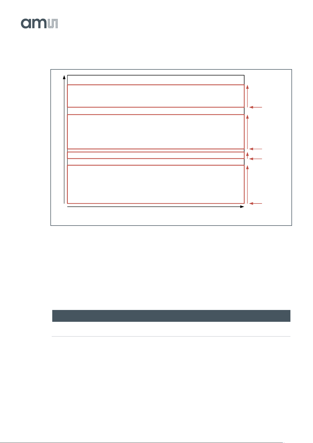
The CMV12000 can read out a maximum of 32 different sub-windows in one read-out cycle. The
location and length of these sub-windows must be programmed in the correct registers. The location
of multiple windows can be random but the windows should not overlap. The total number of lines to
be read out (sum of all windows) needs to be specified in the Number_lines_tot register. The registers,
which need to be programmed for the multiple windows, can be found in the table below.
Figure 55:
Multiple Window Settings
Reg. Name
Address
Bits
Default
Description
Number_lines_tot
1
[15:0]
3072
Total number of lines read out from the sensor (1 to 3072).
Y_start_1
Y_start_2
…
Y_start_32
2
3
…
33
[15:0]
0
Row start address of the window (0 to 3071).
Y_size_1
Y_size_2
…
Y_size_31
34
33
…
65
[15:0]
0
Number of read out lines in the window (1 to 3072).
The default values will result in readout of one window with 3072 lines starting at row 0.
Document Feedback
CMV12000
Functional Description
Datasheet • PUBLIC
DS000603 • v6-00 • 2023-Sep-22
84 │ 46
Figure 56:
Multiple Windows
7.4.5 Mirroring
The image coming out of the image sensor, can be flipped in Y direction. When flipping in Y is enable,
the bottom left pixel (0, 3071) is read out first instead of the top left one (0, 0). The following registers
are involved in image flipping.
Figure 57:
Mirroring Settings
Reg. Name
Address
Bits
Default
Description
Image_flipping
69
[1:0]
0
0: No mirroring
2: Mirror in Y
7.4.6 Subsampling
This mode is only supported in two sided readout. To maintain the same field of view but reduce the
amount of data coming out of the sensor, a subsampling mode is implemented on the chip. Different
subsampling schemes can be programmed by setting the appropriate registers. These subsampling
4096
3072
Y_size_4
Y_start_4
Y_size_3
Y_start_3
Y_size_2
Y_start_2
Y_size_1
Y_start_1
Number_lines_tot = Y_size_1 + Y_size_2 + Y_size_3 + Y_size_4
Document Feedback
CMV12000
Functional Description
Datasheet • PUBLIC
DS000603 • v6-00 • 2023-Sep-22
84 │ 47
schemes can take into account whether a color or monochrome sensor is used to preserve the Bayer
pattern information. The registers involved in subsampling are detailed below. A distinction is made
between a monochrome and color mode and subsampling in Y (skip rows) and X and Y (skip columns
and rows). Subsampling can be enabled in every windowing mode.
Depending on the subsampling and color mode different subsampling schemes are possible.
Figure 58:
Subsampling Schemes
Color Mode
Y-Subsampling
X&Y-Subsampling
Monochrome
Read out 1 row, skip 1,5,9… rows
Read out 1 column and row, skip 1 column and row
Color
Read out 2 rows, skip 2, 6, 10 … rows
Read out 2 column and row, skip 2 column and rows
Y-Subsampling
Below you can find an overview of the settings used for monochrome and color devices together with
some examples for Y-subsampling.
Figure 59:
Y-Subsampling Settings for Monochrome
Reg. Name
Address
Bits
Default
Description
Number_lines_tot
1
[15:0]
3072
Total number of lines read out from the sensor (1 to
1536)
Sub_offset
66
[15:0]
0
Value = (number_of_lines_to_skip +1) /2
Sub_step
67
[15:0]
1
Value = (number_of_lines_to_skip +1)
Sub_en
68
[1]
0
Set to 0
Color
68
[0]
1
Set to 1
Color_exp
68
[3]
1
Set to 1