CMV12000_DS000603_6-00.pdf - 第66页
Document Feedback CMV12000 Functional Description Datasheet • PUBLIC DS000603 • v6 - 00 • 2023 -Sep- 22 84 │ 65 Figure 91 : Additional Required Setti ngs for 8b Mode Mode Number of Outputs Per Side Reg. Address 32 16 8 4…
Document Feedback
CMV12000
Functional Description
Datasheet • PUBLIC
DS000603 • v6-00 • 2023-Sep-22
84 │ 64
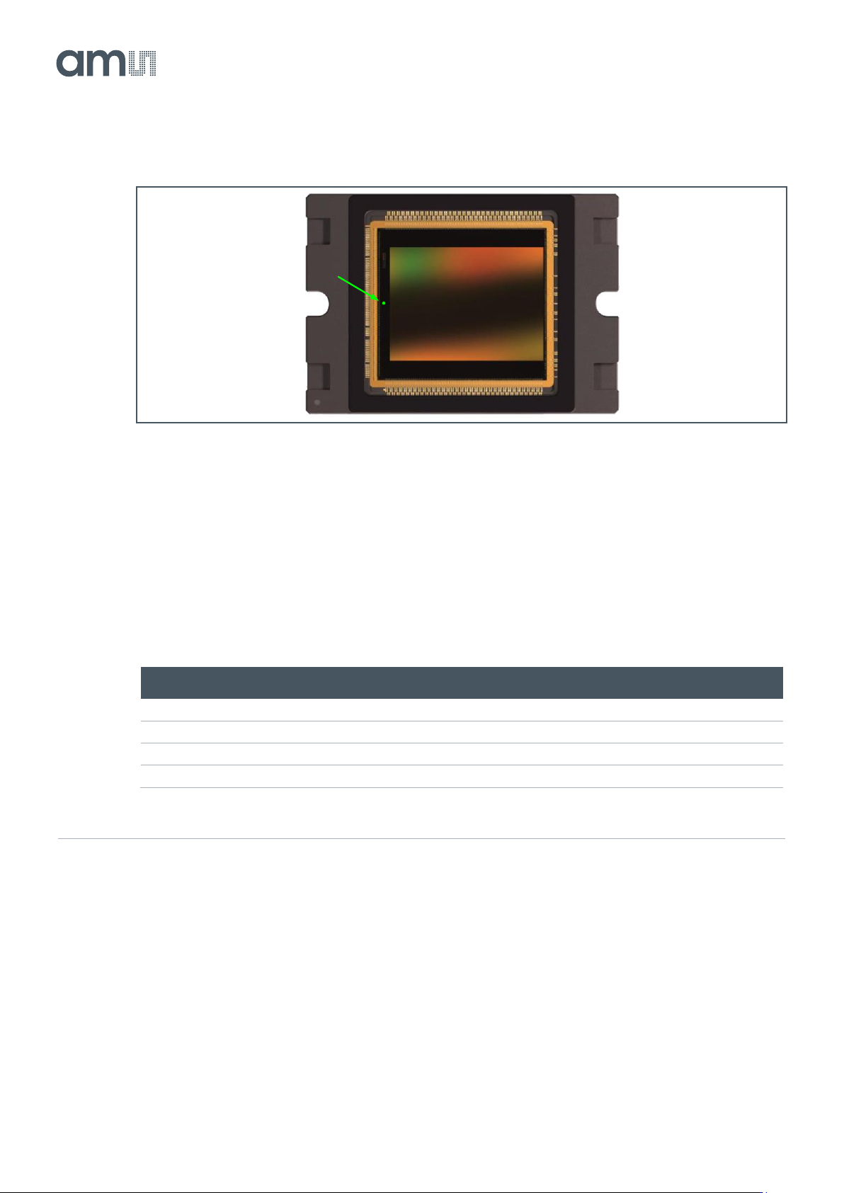
Figure 89:
Temperature Sensor Location
7.6.6 Digital Test Outputs
The sensor has two digital test output pins (TDIG1, TDIG2), which can be used to easily monitor the
sensor state without using the high-speed LVDS control channel.
Use register 123[7:0] to program the output functionality:
Figure 90:
Digital Test Pins
Reg123[3:0]
TDIG1
Reg123[7:4]
TDIG2
0
LVAL
0
DVAL
2
FOT
3
INTE_1
3
INTE_2
5
CLK_PIX (= Output clock divided by the bit mode)
15
FVAL
7.7 Additional Required Register Settings
Depending on the mode or clock speed of the sensor, some additional registers are required to be set.
7.7.1 8b Mode
These settings need to be adjusted per number of channels used per side and normal, X&Y-
subsampling or binning mode.
Document Feedback
CMV12000
Functional Description
Datasheet • PUBLIC
DS000603 • v6-00 • 2023-Sep-22
84 │ 65
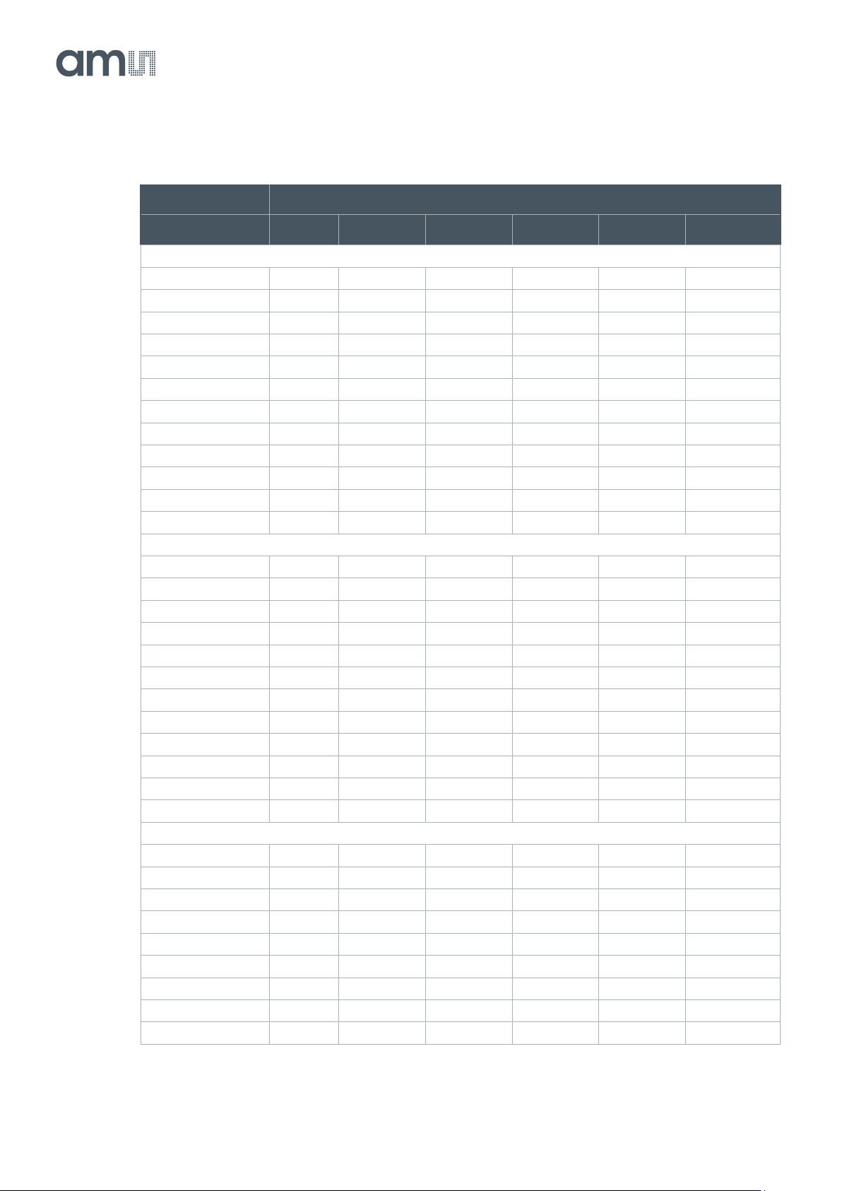
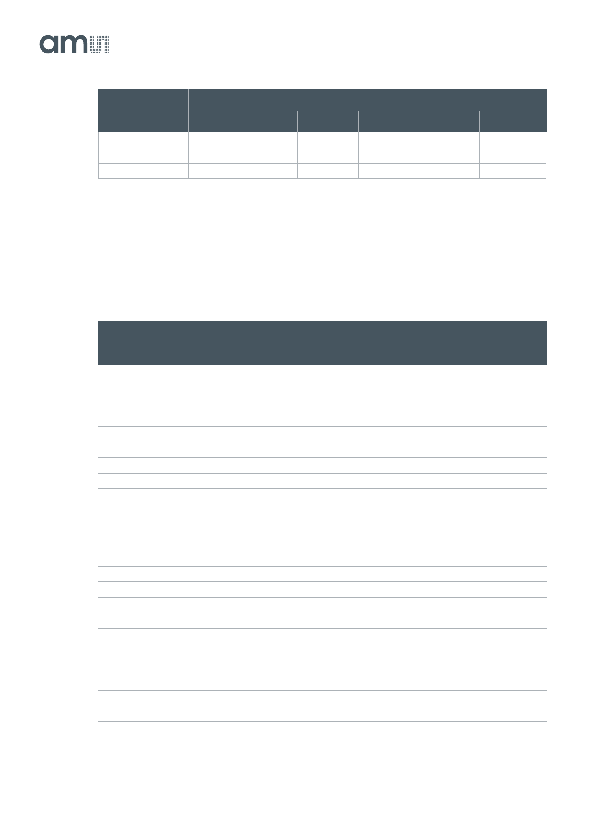
Figure 91:
Additional Required Settings for 8b Mode
Mode
Number of Outputs Per Side
Reg. Address
32
16
8
4
2
1
Normal Mode
82
3618
2082
1058
546
290
290
83
5894
5896
5896
5896
5896
5896
84
143
143
143
143
143
143
85
143
257
515
1031
2063
4127
86
143
257
515
1031
2063
4127
87
510
510
510
510
510
510
88
510
510
510
510
510
510
98
36362
36362
36362
36362
36362
36362
107
11614
11614
11614
11614
11614
11614
109
13416
13416
13416
13416
13416
13416
113
788
788
788
788
788
788
114
90
90
90
90
90
90
X&Y-Subsampling
82
2338
2082
1058
546
290
290
83
5893
5893
5893
5893
5893
5893
84
143
143
143
143
143
143
85
239
257
515
1031
2063
4127
86
119
128
257
515
1031
2063
87
510
510
510
510
510
510
88
510
510
510
510
510
510
98
36621
36621
36621
36621
36621
36621
107
11614
11614
11614
11614
11614
11614
109
13416
13416
13416
13416
13416
13416
113
791
791
791
791
791
791
114
93
93
93
93
93
93
Binning
82
802
802
802
546
290
290
83
5896
5896
5896
5896
5896
5896
84
163
163
163
163
163
163
85
767
767
767
1031
2063
4127
86
191
191
191
257
515
1031
87
360
360
360
360
360
360
88
360
360
360
360
360
360
98
36618
36618
36618
36618
36618
36618
107
11614
11614
11614
11614
11614
11614
Document Feedback
CMV12000
Functional Description
Datasheet • PUBLIC
DS000603 • v6-00 • 2023-Sep-22
84 │ 66
Mode
Number of Outputs Per Side
Reg. Address
32
16
8
4
2
1
109
13416
13416
13416
13416
13416
13416
113
1571
1571
1571
1571
1571
1571
114
90
90
90
90
90
90
7.7.2 10b Mode
These settings need to be adjusted per number of channels used per side and normal, X&Y-
subsampling or binning mode.
Figure 92:
Additional Required Settings for 10b Mode
Mode
Number of Outputs Per Side
Reg. Address
32
16
8
4
2
1
Normal Mode
82
3099
1563
795
539
283
283
83
5893
12805
12805
12805
12805
12805
84
128
128
128
128
128
128
85
128
257
515
1031
2063
4127
86
128
257
515
1031
2063
4127
87
540
540
540
540
540
540
88
540
524
524
524
524
524
98
44812
44812
44812
44812
44812
44812
107
11614
11614
11614
11614
11614
11614
109
13416
13416
13416
13416
13416
13416
113
789
789
789
789
789
789
114
84
84
84
84
84
84
X&Y-Subsampling
82
2843
1563
795
539
283
283
83
5891
5893
5893
5893
5893
5893
84
143
257
257
257
257
257
85
143
257
515
1031
2063
4127
86
71
128
257
515
1031
2063
87
550
480
480
480
480
480
88
540
480
480
480
480
480
98
44815
36620
36620
36620
36620
36620
107
11614
11614
11614
11614
11614
11614
109
13416
13416
13416
13416
13416
13416