M3plus_OperationManual_e.pdf - 第129页
3 - 64 3 Creating the PCB data 5. Creating the mark information 5.4 Vision parameters Vision parameters 27448-5E-20 A: Surface Type This specifies the bright and dark relation between the mark surface and PCB (surroundin…
3 -63
3
Creating the PCB data
5. Creating the mark information
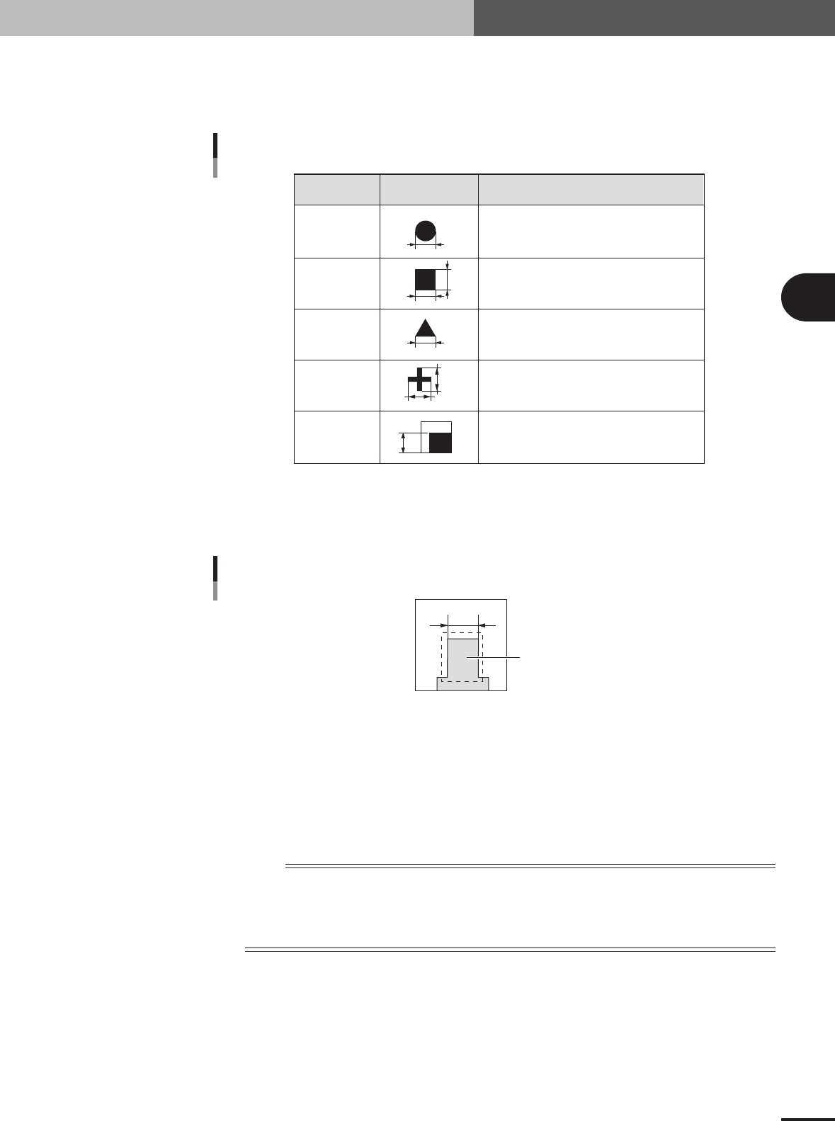
A, B: Mark Out Size X, Mark Out Size Y
Referring to the table below, enter the correct value in the mark size. This parameter is not
displayed when "Mark Type" of the Basic parameters is set to "Badmark". The Search Area
parameters appear instead.
Example Mark Out Size settingShape Type
X
X
Y
Y
Enter the diameter.
Enter the length of each side.
Enter the length of one side.
Enter the X length for the MarkOutSize X, and
the Y length for the MarkOutSize Y.
Enter the length of the shorter side displayed
within the search area.
Circle
Square
Triangle
Sp. Shape
Corner
Mark Out Size settings
25413-5E-20
Mark Out Size setting for special mark
If using a special mark with two or more edges as shown below, enter the size of the shortest side of
the rectangular area to be detected.
Rectangular area to be detected
Mark Out Size setting for special mark
23439-5E-20
C: Area
Enter the area of the mark in units of square millimeters. This parameter is displayed only when
"Shape Type" of the Shape parameters is set to "Sp. Shape".
D: Outline
Enter the perimeter length of the mark in units of millimeters.
This parameter is displayed only when "Shape Type" of the Shape parameters is set to "Sp. Shape".
n
NOTE
A recognition error may occur due to environmental conditions such as illumination. In such cases, enter a larger
value than previously used for"Tolerance" of the Vision parameters, or set the tolerance to 100%, then perform
the vision test in the Mark Adjust mode and enter the obtained data on the area and perimeter. (The mark area and
perimeter values are displayed after the vision test is complete.) Return the tolerance to the original value after the
data is obtained.
3 -64
3
Creating the PCB data
5. Creating the mark information
5.4 Vision parameters
Vision parameters
27448-5E-20
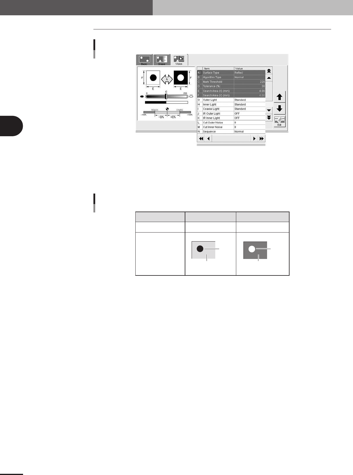
A: Surface Type
This specifies the bright and dark relation between the mark surface and PCB (surrounding area).
Select "NonReflect" when the mark is darker than the surrounding area, and select "Reflect" when
the mark is brighter than the surrounding area, as shown below.
NonReflect
PCB is brighter than mark.
Reflect
Mark is brighter than PCB.
Setting
Brightness comparison
Image
PCB
Mark
PCB
Mark
Surface Type settings
25414-5E-20
B: Algorithm Type
There are 5 algorithm types selectable for mark recognition.
• Normal
In typical recognition, all types of marks should be set to "Normal". Try setting to other parameters
if the mark cannot be recognized with the "Normal" setting.
• Special 1
Select this if the mark cannot be recognized by the "Normal" setting.
• Special 2
Select this if the mark which cannot be recognized by the "Normal" setting has a cutout area.
• PTRN Outline, PTRN GrayLev, PTRN Whole
Select these parameters when the Shape Type parameter is set to "Pattern". For more details, refer
to "3.1 Pattern matching" in chapter 4.
C: Mark Threshold
This is the threshold level for binary image used to recognize the mark. An optimum threshold
level can be found in the Mark Adjust mode explained later in this section.
D: Tolerance
This specifies a tolerance percentage for the mark size when the mark is recognized with the vision
system. (Typically this should be set to "30".)
3 -65
3
Creating the PCB data
5. Creating the mark information
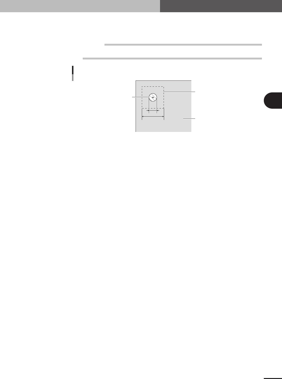
E: Search Area X
As a general guide, set this parameter to the mark diameter plus 3mm. For example, when the mark
diameter is 1mm, set this parameter to "4mm" as shown below. If other marks (such as resist, silk
print, other patterns) exist in this search area, make the Search Area setting smaller.
Reference
The Search Area parameter is not displayed on the Vision tab screen when "Mark Type" of the Basic parameters
is set to "Badmark".
1
4
Search Area
Mark
PCB
Search Area
23440-5E-20
G to K: Light level
Lighting for recognizing a mark is divided into several zones. Light level in each zone is displayed
here. Optimum light levels can be found in the Mark Adjust mode explained later.
L, M: Cut Outer Noise, Cut Inner Noise
These parameters are used to cut the noise that usually appears within or outside the mark image
when the mark is recognized as a binary image. Optimum noise cut levels can be found with the
Mark Adjust mode explained in the next section.
N: Sequence
Set to "Normal" in most cases. If the recognition speed is important select "Quick", or if recogni-
tion accuracy is important select "Fine".