M3plus_OperationManual_e.pdf - 第90页
3 - 25 4. Creating the component information 3 Creating the PCB data •S O J This is for components having the same shape leads and same number of leads in the E and W direction like "SOP", but whose leads do no…
3 -24
3
Creating the PCB data
4. Creating the component information
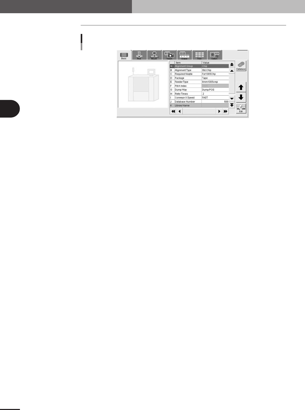
4.2 Basic parameters
Basic parameters
27412-5E-20
A: Alignment Group
Select from "Chip", "IC", "Ball", "Connector" or "Special".
B: Alignment Type
Specify the type of component by referring to the descriptions below.
Chip
• Std.Chip (Standard chip)
This setting does not identify the component, but detects the four corners of the component and
then calculates the center and angle of the component. Select this setting first when recognizing
box type chips. If the component cannot be recognized by this setting, try using "Sp.Chip" or
"Small Chip".
•Melf Chip
This is specially for Melf chips.
• Bare Chip
This is specially for bare chips.
• Cylinder
This is suited for components with a cylindrical shape and no direction.
• Sp.Chip (Special chip)
This setting has a parameter used to recognize "Lead Width" in addition to the "Std.Chip" setting.
Select this to recognize box type chips which cannot be recognized correctly by the "Std.Chip"
setting. If it is still difficult to recognize the component by this setting, try with "Odd.2Ends".
• Small Chip
This is suited for small chip components such as 0603 whose light-reflecting area is smaller than
the actual size.
IC
• Odd.2Ends
This mode has a parameter used for recognizing the lead width and length by using "LeadWidth"
and "ReflectLL." in addition to the "Std.Chip" mode. This mode is suited for recognizing box type
chips which cannot be recognized by "Std.Chip" or "Sp.Chip".
• Mini Tr/SOT
This mode is for mini mold components with the same shape leads in the N and S direction, but
whose number of leads in each direction is different.
•P-Tr
This mode is for components having leads in the N and S direction, and whose number of leads in
each direction is different like "Mini-Tr/SOT", and also the shape of opposing leads is different.
• SOP
This is for components having the same shape leads and same number of leads in the E and W
direction, and whose leads protrude out from the molded body.

3 -25
4. Creating the component information
3
Creating the PCB data
•SOJ
This is for components having the same shape leads and same number of leads in the E and W
direction like "SOP", but whose leads do not protrude out from molded body.
• QFP
This is for components having the same shape leads in four directions of N, S, E and W, and the
same number of oppositely positioned leads (N to S and E to W), and whose lead protrudes out
from molded body.
• PLCC
This is for components having the same shape leads in four directions of N, S, E and W, and the
same number of oppositely positioned leads (N to S and E to W) like "QFP", but whose leads do
not protrude out from molded body.
• OffLead
This is used for components which can be defined by "Con-NSEW" but some of the leads are
removed. Input this setting for each direction.
Ball
• Simple BGA
This is specially for BGA components. The number of ball leads can be checked, but the ball lead
positions and nicks are not checked.
• BGA
This is specially for BGA components. The ball lead positions can be edited to check the lead
positions and nicks.
• FlipChip
This is specially for flip chip components and can be used only when a vision camera with a side
lighting unit is used.
Connector
• Con-E (Connector E)
This is for components having the same leads only in the E direction.
• Con-NSEW (Connector NSEW)
This setting is suited for components having leads in four directions of N, S, E and W, but the
number of leads and their shape in each direction are different. Only one type of lead shape can be
set for each direction.
• Odd.Con
Use this setting for connectors suitable for "Con-E" having off leads.
• Special
This can be used for components having irregularly arranged leads. For example, components
having leads in four directions of N, S, E and W like "Con-NSEW", but whose number of leads and
the shape in each direction are different. Although "Con-NSEW" allows setting only one type of
lead shape in each direction, "Special" allows setting two types, making it usable for various
components with irregular shapes. This setting cannot be used with the lead coplanarity function.
Odd.Chip
• Odd.Chip
This setting automatically determines whether to recognize a component as "white" or "black",
making it suited for components such as bare chips which are difficult to judge as reflective or
non-reflective against the background (PCB). This mode is also appropriate for BGA components
with a light reflective portion on the body.
• AsMark
This setting recognizes components as a mark and is therefore suited for specially shaped compo-
nents.
• Sp. Quad
This is used for square or rectangular components which reflect light at the four sides of the
package making it difficult to distinguish the leads from the package.
• Gravity
This detects the center-of-gravity of a target (black or white) in the specified area, allowing
reliable recognition of various components with irregular shapes. When using this setting, test-
mount the component after setting the data, and check the mounting shift (distance from center of
mounting position to center of the component). Then enter the shift amounts in "Cntr. Offset XYR"
of the Shape parameters.
3 -26
3
Creating the PCB data
4. Creating the component information
• Ignore
This does not perform image processing.
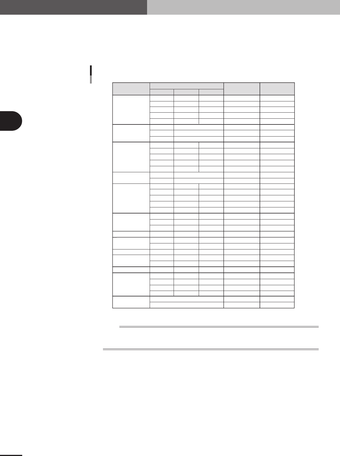
C: Required Nozzle
Select the optimum nozzle that matches the component size from among the nozzle types for chip
components. When the parameter values are copied from the database, use the default setting.
Component
Size (mm)
Box type chip
Cylindrical chip
(Melf type
component)
Ceramic
capacitor
Tantalum
electrolytic
capacitor
Aluminum
electrolytic
capacitor
SOP
PLCC, QFP, BGA
Chip inductor
Semi-variable resistor
Mini-mold
transistor
Power transistor
Chip film capacitor
Melf type
capacitor
LWT
Nozzle type
Required
Nozzle Setting
Typical component and suitable nozzles
0.60
1.00
1.60
2.00
3.20
2.00
3.45
5.90
1.50
2.00
3.20
3.20 to 4.50
5.60
3.40
5.90
2.90
3.80
4.70
6.00
7.30
4.30
6.60
10.00
7.30
3.20
4.50
4.50
2.90
4.00
4.60
5.00
7.60
10.10
12.60
0.30
0.50
0.80
1.25
1.60
0.80
1.25
1.60
2.50 to 3.20
5.00
1.60
2.90
2.60
3.20
4.30
4.30
6.60
10.00
5.30
2.50
3.20
3.80
1.50
3.00
2.60
4.50
4.50
4.50
5.70
0.25
0.50
0.50
0.50
0.60
0.80
1.25
1.25
1.50 to 1.90
1.90
1.60
1.60
2.10
2.50
2.80
5.70
5.70
10.50
3.25
2.00
3.20
2.40
1.10
1.80
1.60
1.50
1.50
1.50
1.50
Type 81A
Type 82A
Type 82A
Type 84A
Type 82A
Type 82A
Type 82A
Type 86
Type 82A
Type 82A
Type 82A
Type 83A
Type 83A
Type 82A
Type 8SA
Type 82A
Type 83A
Type 83A
Type 83A
Type 83A
Type 83A
Type 83A
Type 84A
Type 83A
Type 83A
Type 83A
Type 83A
Type 83A
Type 83A
Type 83A
Type 83A
Type 83A
Type 84A
Type 84A
Type 83A
Type 84A
For0603CHIP
For1005CHIP
For1608CHIP
For2125CHIP
For3216CHIP
ForMELF S
ForMELF M
ForMELF L
For1608CHIP
For2125CHIP
For3216CHIP
For4532CHIP
For5650CHIP
ForMELF M
ForMELF L
For3216CHIP
For4532CHIP
For5650CHIP
For7343CHIP
For7343CHIP
ForALC S
ForALC M
ForQFP 20mm
For7343CHIP
For4532CHIP
For4532CHIP
ForVR L
For3216CHIP
For4532CHIP
For5650CHIP
ForSOP 10mm
ForSOP 10mm
ForSOP 20mm
ForSOP 20mm
ForSOP 10mm
ForQFP 20mm
5x5 to 10x10mm
10x10 to 31x31mm
(up to 24x24 for Heads 1 and 4 )
1.25
1.35
2.20
1.50
2.20
25001-5E-20
n
NOTE
If using a custom nozzle designed for the connector, select the corresponding type from among "Sp. Nozzles A to
F". In other cases, select the optimum nozzle that matches the connector size from among the nozzle types for
SOP components.
D: Package
Select the type of component feed.
"Tape"
Select this setting when using a tape feeder which supplies components on paper tape, embossed
tape or adhesive tape.
"Stick"
Select this setting when using a stick feeder such as a stack stick feeder or high-speed stick feeder.
"Bulk"
Select this setting when using a bulk cassette feeder.
"Tray"
Select this setting when supplying components from Tray Shuttle Feeder (TSF1).