M3plus_OperationManual_e.pdf - 第231页
B - 18 B Alignment T ype glossar y 2. Alignment T ype glossary 2.2.5 Special rectangle (Sp. Quad) recognition mode Rectangular and square shaped components can be recognized with this algorithm. 1. Contour edge detection…

B -17
B
Alignment Type glossary
2. Alignment Type glossary
Lead Number S1 Set the number of leads.
ReflectLL S1, Lead Width S1 Set the size (surface area) of the lower lead section. If a
rectangle, specify a value of the lead length multiplied by
the lead width. If a circle, specify the diameter of the circle
with the lead width and a lead length equal to 0.
Lead Pitch S1 Set the pitch of the lower lead section.
Find PosX S1, Find PosY S1 Set the center-of-gravity position of the lower left lead
section.
Lead Number S2 to Find PosY S2 Set the group 2 data when the number of lead groups is 2.
Set 0 when the number of lead groups is 1.
Lead Group E Set the number of lead groups (1 or 2).
Lead Number E1 Set the number of leads.
ReflectLL E1, Lead Width E1 Set the size (surface area) of the right lead section. If a
rectangle, specify a value of the lead length multiplied by
the lead width. If a circle, specify the diameter of the circle
with the lead width and a lead length equal to 0.
Lead Pitch E1 Set the pitch of the right lead section.
Find PosX E1, Find PosY E1 Set the center-of-gravity position of the upper right lead
section.
Lead Number E2 to Find PosY E2 Set the group 2 data when the number of lead groups is 2.
Set 0 when the number of lead groups is 1.
Lead Group W Set the number of lead groups (1 or 2).
Lead Number W1 Set the number of leads.
ReflectLL W1, Lead Width W1 Set the size (surface area) of the left lead section. If a
rectangle, specify a value of the lead length multiplied by
the lead width. If a circle, specify the diameter of the circle
with the lead width and a lead length equal to 0.
Lead Pitch W1 Set the pitch of the left lead section.
Find PosX W1, Find PosY W1 Set the center-of-gravity position of the upper left lead
section.
Lead Number W2 to Find PosY W2 Set the group 2 data when the number of lead groups is 2.
Set 0 when the number of lead groups is 1.
Others Set to 0.
B -18
B
Alignment Type glossary
2. Alignment Type glossary
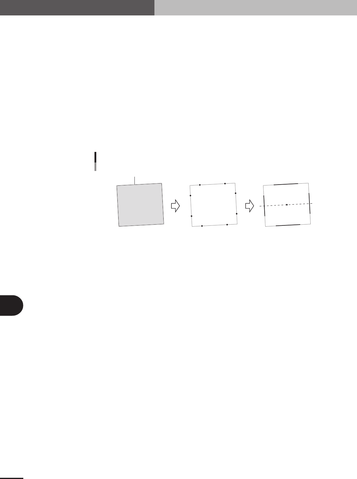
2.2.5 Special rectangle (Sp. Quad) recognition mode
Rectangular and square shaped components can be recognized with this algorithm.
1. Contour edge detection
Extracts the contour of the component.
2. Detection range setting
Sets the respective detection range on the top, bottom, left, right on the detected contour. Which
edge (top, bottom, left or right) to detect can be selected by making a parameter setting.)
3. Application of line
Applies a line to the edge coordinates within the range that was set. This process is run for all 4
directions. (Finds a line according to which edge (top, bottom, left or right) is being detected.
4. Component center and tilt detection
The tilt of the 4 lines that were found is averaged and taken as the component tilt. The center-of-
gravity of the edge being measured is the component center. (The tilt is found with the correspond-
ing method for whichever edge is being measured {top, bottom, left, right}.
P1
P5
P6
P7
P0
P2
P3
P4
P1
P5
P6
P7
P0
P2
P3
P4
Special rectangle
Detecting the contour
23B07-5E-20
■ Special rectangle recognition
Alignment Group Special
Alignment Type Sp. Quad
Comp. Threshold Set the binary level. (If set to 0, the binary level is set
automatically.)
Comp. Tolerance Set the shape dimension tolerance.
Search Area Set the detection range.
Body Size X Set the component size.
Body Size Y Set the component size.
Body Size Z Set the component thickness.
Lead Number W1 Set to 0.
Surface Type Select "Reflect" (reflective surface) or "NonReflect" (mat
surface).
Cut Outer Noise Select from 0 to 7.
Cut Inner Noise Select from 0 to 7.
Noise Cut Order Select "Inner" or "Outer".
Lead Number N Set a number other than 0 if you do not want to detect a
straight line in this direction.
Lead Number S Set a number other than 0 if you do not want to detect a
straight line in this direction.
Lead Number E Set a number other than 0 if you do not want to detect a
straight line in this direction.
Lead Number W Set a number other than 0 if you do not want to detect a
straight line in this direction.
B -19
B
Alignment Type glossary
2. Alignment Type glossary
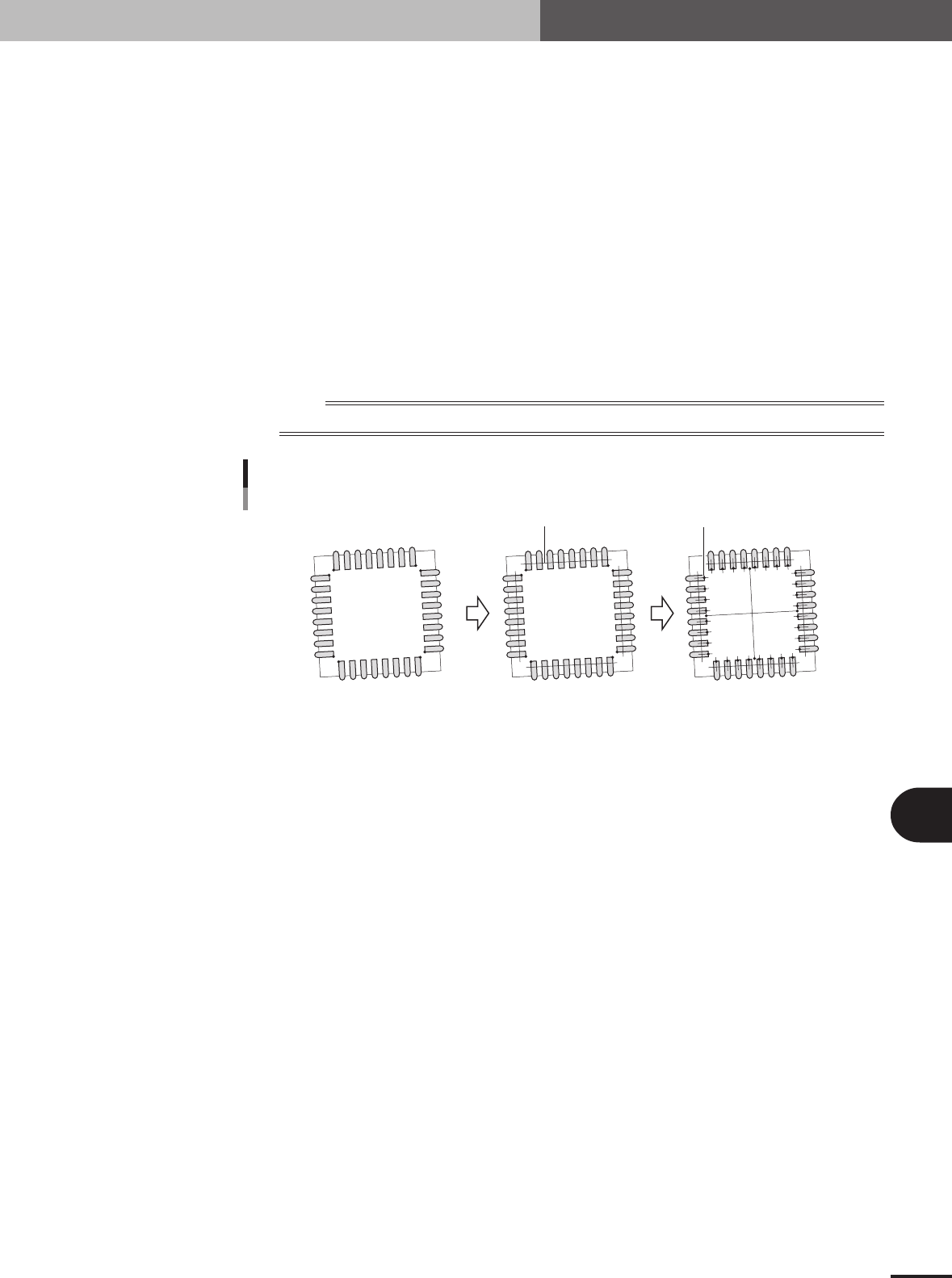
2.2.6 PLCC (SOJ) base recognition mode
In PLCC (SOJ) recognition, this mode is provided to detect the base of the lead.
1. Lead detection
This mode finds P0 to P7 in the direction of the lead base as shown in the figure below.
2. Lead center setting
Finds the lead center from the distribution (density) on the line where P0 to P7 are offset by a
specified value.
3. Lead base edge detection
Detects the edge of the lead base on the line passing through the center of the leads and perpen-
dicular to the line used to find the distribution (density).
4. Component center and tilt detection
All of the lead base positions are averaged to obtain the component center, and the tilt of the lines
joining the centers of the opposing sides are averaged and taken as the component tilt.
n
NOTE
The Search Area must be set so that the lead base position can be detected.
P1
P0
P4
P6
P5
P7
P3
P2
P1
P0
P4
P6
P5
P7
P3
P2
PLCC (SOJ) base recognition
Offset line
Lead center Edge of base
23B08-5E-20
■ PLCC base recognition
Alignment Group Special
Alignment Type Special
Comp. Threshold Set the binary level. (If set to 0, the binary level is
automatically set to 30.)
Comp. Tolerance Specify the shape dimension tolerance.
Search Area Set the detection range.
Body Size X Set the component size.
Body Size Y Set the component size.
Body Size Z Set the component thickness.
Cntr. Offset X (mm)
Cntr. Offset Y (mm)
Cntr. Offset R (deg)
Ruler Offset N Set in pixels the amount to offset the detection line in the
N direction.
Ruler Offset S Set in pixels the amount to offset the detection line in the S
direction.
Ruler Offset E Set in pixels the amount to offset the detection line in the
E direction.
Ruler Offset W Set in pixels the amount to offset the detection line in the
W direction.
Ruler Width Set the width of the lead detection line.
Algorithm Special 1