M3plus_OperationManual_e.pdf - 第265页
4 - 4 4 Inspection and maintenance w ork 4.3.3 Supplementary description of the overrun sensors and origin sensor Visually check whether the overrun sensors (+/-) and origin sensor get dirty as explained below. 1. Press …

4 -3
4
Inspection and maintenance work
4.3.2 Applying grease
To apply grease to the shuttle axis ball screw and linear guide, proceed as follows.
1
Turn off the mounter power switch.
2
Detach the TSF1 from the mounter.
3
Open the TSF1 upper safety cover.
4
Remove debris from the ball screw and linear guide.
1.Move the shuttle to one end of the axis and wipe clean the ball screw surface and
lead groove and the linear guide surface and sliding grooves with a shop cloth.
2.While moving the shuttle to the opposite end of the axis, wipe the ball screw
surface and lead groove and the linear guide surface and sliding grooves with a
shop cloth.
c
CAUTION
Use a clean, lint-free shop cloth to wipe the ball screw and linear guide. Check that there is no
lint residue on the wiped area.
5
Apply grease to the ball screw and linear guide.
Apply grease by hand uniformly over the ball screw surface and lead groove and the
linear guide surface and sliding grooves.
6
Remove excess grease.
After moving the shuttle back and forth a few times between the ends of the shuttle
axis, wipe away excess grease.
7
Install the TSF1 to the mounter.
8
Spread the grease over the entire sliding area.
Start the mounter, perform return-to-origin and move the TSF1 shuttle in JOG mode to
spread the grease over the entire sliding area.
c
CAUTION
Check that no abnormal noise is heard during return-to-origin and JOG operation.
Recommended grease
Name
Part name Part No.
AFB grease GREASE, AFB LG0-M86A4-00X
75401-V5-00
4 -4
4
Inspection and maintenance work
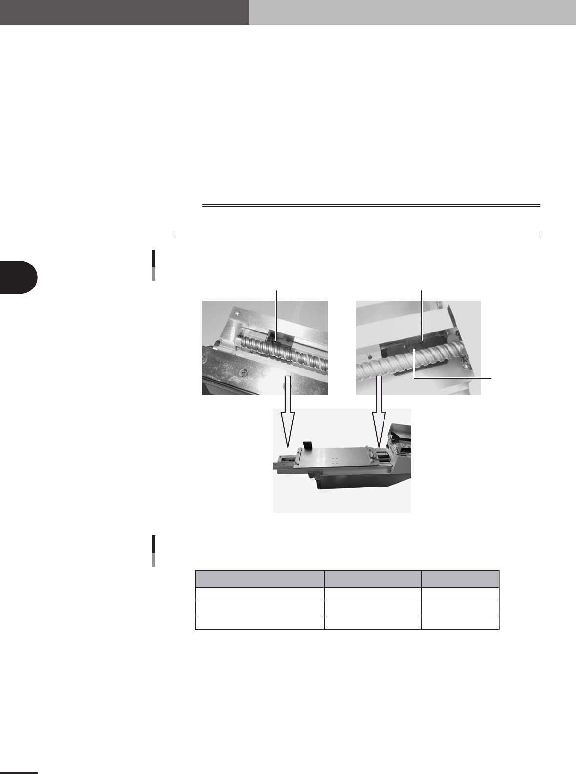
4.3.3 Supplementary description of the overrun sensors and origin
sensor
Visually check whether the overrun sensors (+/-) and origin sensor get dirty as explained
below.
1. Press the emergency stop button on the TSF1.
2. Open the TSF1 upper safety cover.
3. Move the shuttle by hand to the axis end on the operation switch panel side.
4. Check that the overrun sensor (+) works correctly.
5. Move the shuttle by hand to the axis end on the mounter side.
6. Check that the overrun sensor(-) and the origin sensor works correctly.
n
NOTE
If the sensor does not work correctly due to dust deposition on the sensor, then wipe clean the sensor with a
cotton swab stick.
Sensor position
Origin sensor
Overrun sensor (-)
Overrun sensor (+)
73402-5V-00
Sensor list
Name Part name Part No.
Overrun sensor (+)
Overrun sensor (-)
Origin sensor
SENSOR,1 Assy
SENSOR,2 Assy
HNS,PB MOTOR PI
LC2-M5 1F4-00X
LC2-M5 1F5-00X
LC2-M5 1FA-00X
75403-5V-00
e